Developer Notes: Working with SQLite in C++
My personal notes on using SQLite with C++. Not intended to be a tutorial. Source
sqlite3* dba reference to the database object. Main connection point.sqlite3_open(path, &db)to create or connect to an existing databaseTransaction occur via regular SQL queries. Standard statement wrapped as
const char*strings.Example:
const char* query = "INSERT INTO plants (name, variety, botanical_name) VALUES (?, ?, ?)";Standard Transaction pattern:
- Check if db pointer is valid, else early return
- Write query as string
- Execute as Integer
- If successful, report, else return
- Transaction types:
int sqlite3_exec( sqlite3 *db, /* An open database */ const char *sql, /* SQL to be evaluated */ int (*callback)(void*,int,char**,char**), /* Callback function */ void *arg, /* 1st argument to callback */ char **errmsg /* Error msg written here */ );standard execution one step execution wrapper. Not for user input or complex queries
int sqlite3_prepare_v2( sqlite3 *db, /* Database handle */ const char *zSql, /* SQL statement, UTF-8 encoded */ int nByte, /* Maximum length of zSql in bytes */ sqlite3_stmt **ppStmt, /* OUT: Statement handle */ const char **pzTail /* OUT: Pointer to unused portion of zSql */ );Used to compile a single query. Thread safe prepared statement.
Requires
sqlite3_stmt*variable. ReturnSQLITE_OKand serves as the output pointer for executed transactionsint sqlite3_step(sqlite3_stmt*)- evaluates a prepared statement and returns the row, done or an errorint sqlite3_column_int(sqlite3_stmt*, int col)const unsigned char* sqlite3_column_text(sqlite3_stmt*, int col)Used to access data from the columns. 0-based index
int sqlite3_reset(sqlite3_stmt*)- clears execution stateint sqlite3_finalize(sqlite3_stmt*)- destroys object and frees memory required for transaction
sqlite3_stmt*pointer to a prepared statement. Used to compile the SQL query, bind variables, execute the query and free the compiled objectBindings:
int sqlite3_bind_int( sqlite3_stmt *pStmt, /* Prepared statement object */ int idx, /* Index of the SQL parameter (1-based) */ int val /* The integer value to bind */ );Binding an integer via a placeholder. Example 4.
int sqlite3_bind_text( sqlite3_stmt *pStmt, /* Prepared statement object */ int idx, /* Index of the SQL parameter (1-based) */ const char *zVal, /* Pointer to the text string data */ int nBytes, /* Byte length of zVal or negative value */ void (*xDel)(void*) /* Memory destructor callback function */ );Binding text
- Types:
INTEGER=intint64_t- use 64 bit to prevent overflowREAL=doublefloatTEXT=stringchar*BLOB=vectorconst void*- example: images or non standard dataNULL=nullptr
- Memory Life cycles and Safety rules
- Binding destructors, ensure release of memory
SQLITE3_TRANSIENT- for string for example that can changeSQLITE3_STATIC- data in permanent buffer- Data in
sqlite3_column_textsqlite3_column_blobis owned by the statement object and goes out of scope one you can the preceding executions. - Always copy the data
- Resource leak prevent
- Always close the connection
sqlite3_close()to close the connection and free resources
- Error Handling
- Transactions return integer result codes
SQLITE_OK- 0 = SuccessSQLITE_ROW- 100 = Step Successful, row foundSQLITE_DONE- 101 = Step completeSQLITE_BUSY- 5 = db locked by another process or threadSQLITE_CONSTRAINT- 19 = constraint violation, foreign key, unique, not null etcSQLITE_MISUSE- 21 = functions out of order- Use
sqlite3_busy_timeout()to reopen connection when busy or use mutex
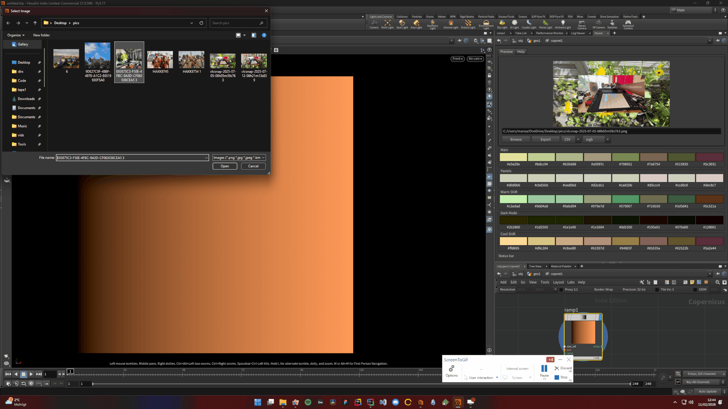
Hywall - Colour Palette From Image In Houdini
Hywall is a tool for generating inspiring colour palettes from images in Houdini. Generates 5 palette variants: Main, Pastels, Warm Shift, Dark Mode, and Cool Shift. GITHUB
Features:
Generate colour palettes from any image
5 palette variants: Main, Pastels, Warm Shift, Dark Mode, Cool Shift
Click a colour swatch to copy hex to the clipboard
Click a palette row to apply as a colour ramp to a selected node (Node needs to have a ramp)
Export palettes to CSV, JSON, GPL, CSS
Colour space selector for exports (sRGB, ACEScg, OKLab, etc.)
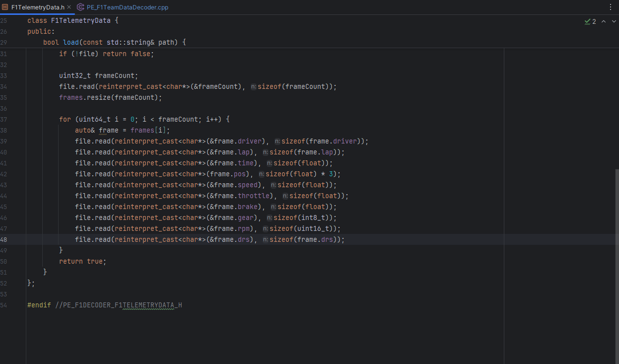
Encoding F1 Telemetry as Binary for Houdini
I built a pipeline to bring Formula 1 telemetry data into Houdini as point attributes. It includes a python shelf tool for querying the Fast F1 telemetry database and writing out the requested data as binary and a custom HDK node for decoding the binary data in attributes on points.
As a fan of F1, I have always wanted to play around with race data inside of Houdini and come up with interesting visualizations and simulations. The problem is that F1 data can be very large and storing or interpreting it over time can be computationally costly. A single race contains thousands of data points on everything for engine rpm to air temperature. There is also a need to preserve the high level of precision in the data set. My solution is to transform the output from the database into binary. I got my inspiration when researching the WAV file header, which does a similar thing with audio data.
How It works
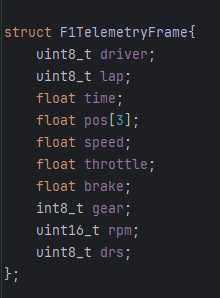
We decide on a structure of data that we want from the database
Determine the data types for the requisite fields in the database
Convert the strings from the database into binary with struct.pack in python
Write out a .bin file in the custom format
In C++, load file and iterate over telemetry frames
Unpack attributes into a struct matching the python layout
Create points and assign attributes
Data Source
FastF1 is a python library that gives you access to historical f1 telemetry. Through its API, you can explore and visualize races, weather conditions, championship standings, etc.
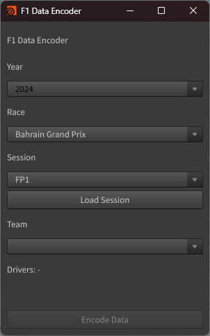
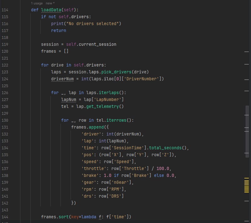
Python SOP Tool
This is an interface for querying the FastF1 database, you select the year , the race and team to export the entire session of both drivers. We then write that data out as binary. The interface is Houdini’s standard Qt interface.
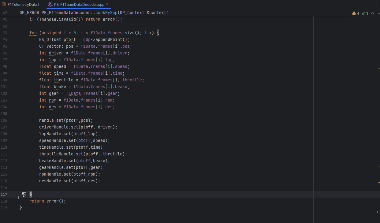
HDK node
Here we unpack the binary data from the file and create points to store the telemetry as attributes. We read in the file and cast from binary into the requisite data type for our attributes. The result is an outline of the track with each point representing a slice in time.
Why Binary
There is a bit more setup but you make up for it with speed. It is also reasonable to assume that you do not need every data point to the database, so designing the shape you want can saves you space and time. Older races can be quite smaller, Japan 2022 being 875kb. Newer data seems to have a higher sampling frequency so Bahrain 2024 ended up being 2.4mb. One limit of the transformation is that fast f1 has to cache the database somewhere locally. There could be work around this but is acceptable int his context.
Project Looking Glass - Houdini Project Launcher Devlog 02 - Release Version
Version 1.0 of my Houdini launcher is now done. Download the installer here to try it out on Windows. Please send me your feedback
What is Project Looking Glass
Project Looking Glass is designed to be a database for organising, launching, and versioning Houdini Projects. My previous blog post details how it works. In this post I will talk about developing the first release version.

Key Features
Categories
Search
Project Context Menu
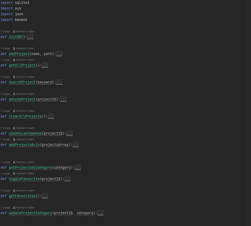
SQLite database
Tech Stack
I also added an error screen to handle configuration issues. The entire tech stack is
Godot - Ui/ main app
Python/ SQLite - Database
PyInstalller - database executable
Inno Builds - Windows Installer


A useful database
I decided to ditch the json list for sqlite database as it would make searching categories, filters or tags much easier, plus all the other obvious benefits of an actual database structure. In python I created a command line interface to execute my database transactions that are called from the app in godot. Python creates a database in the root director and passes data via various transactions to the user interface. It is bundled as an executable with PyInstalller.
In Godot I then run these queries to search the database and organize my projects in categories, these are preset for now and the user would be able to add or edit them. The database adds about 5ms on startup but all other queries are fast with under 10,000 projects. Folder scanning is done in bulk via a single transaction
The next key feature was the context popup menu for user operations on projects. It helps keep the interface minimal. Users can set categories on favourites, open and remove projects from the database.

Issues
I decided to remove project creation as it can be a bit tricky for a few reasons. It will be best to implement this on a separate thread as the process can hang the launcher. Additionally there is the problem on Hython. I cant bundle my python houdini project creation script and redistribute so I might have to explore other options for interfacing what houdini. If you have any suggestions, please let me know.
There are also some architectural and UI things that need doing. The window is not fully responsive yet. The next thing I want to think about is sorting the list and git integration. For the latter, I am yet to decide the depth, I am not interested in duplicating a git client.
Please send me any questions or issues you may encounter if you end up using the application, I might share my source code at the end.
Project Looking Glass - Houdini Project Launcher Devlog 01
This blog post is intended to document the first phase of my development of Project Looking Glass - A Houdini Project manager for native platforms.

What is Project Looking Glass
Project Looking Glass is designed to be a database for organising, launching, and versioning Houdini Projects. It is built with Godot. This first post details my motivation and the components that make up the alpha version of this application. The application is in early development, but I hope to eventually release it. You can watch a demo here
Motivation
Houdini is great, but the native Houdini launcher isn't designed around project management. I wanted a place to organise my Houdini scenes besides my native file explorer. I have a range of different projects and it can be hard to find that one scene that has the vex snippet I am looking for. I wanted to create a centralised database I could search quickly and could then connect to source control as well.
Additional motivation comes from my desire to keep practising designing and developing desktop applications. This is an application I actually need for my own work. I have recently been exploring Godot for things beyond games, and a project like this is very attainable with it as the backbone. Eventually, I will expand some more on why Godot and not Electron or Qt.
Minimum Viable Product
I started with a list of the essential features of a project launcher. My main problem with my library of Houdini projects is categorisation. I want to be able to sort my projects into relevant tags so I can find projects quickly, as well as decipher relevant info like version control status at a glance. It should dissolve the friction of navigating the file system and get you into the project quicker than other project categorization methods. The main problem is a lack of quick configurable categorization. Good tooling should be able to resolve this.
I then started prototyping in Godot, initially scripting an interface with the key functions any launcher should have, such as loading the target application - Houdini, scanning folders for specific files and creating one record of these files in an indexable list or sorts.
After I had the core functions written, I then designed a mock-up of the user interface, heavily inspired by Apple iPad design language. What was left was assembling this mock-up with Godot's UI components. The result is a fully responsive and functional application


Features
User can add single projects to the database
User can scan folders for Houdini projects to add to the list
User can create new Houdini projects
User can Launch Houdini projects
User received feedback on operations via the status bar
User can set with version of the target application to launch
How it works
The architecture of an application launch is quite simple. We have a target application and a target file. We use the native OS process via the command line/terminal to launch the target application from our user interface interaction, passing the file and any other arguments. That is essentially it.
For creating projects, I take advantage of Hython, Houdini’s Python shell, to set the proper directories. A similar pattern I will describe later also works for the database The rest is just UI and binding functions
Coming Up
Migrating the database from JSON to SQLite with Python
Implementing effective categorisation and search
UI responsiveness
Grid View?
Procedural Approach To Digital Painting in Houdini with Copernicus
I want to share some examples and insights into my process of turning 3D scans into digital paintings. The Images produced in this post are made from image compositing 3D renders in SideFX Houdini in the Copernicus context.
The Images starts off with 3D scans made with Reality Capture. In Houdini, I prepare them for rendering in Karma by applying a material in the SOPs context. Each composition is then brought into Solaris for rendering and image processing
Image - Digital Painting
My focus is on an oil painting style and an illustrated/cell-shaded look and these are the techniques I will be discussing.
The process of going from realistic shading to stylized rendering involves the following transformations:
First is extract AOVs such as Normal, UV, Depth, Shadow, and Cryptomate Objects, for isolating specific data channels on the images before the final composite image is produces
Then Process these buffers in a COPs node, either as a Slap Comp or a file import with the AOVs. The latter gives you faster iteration tie as all data is cached on disk.
Then Render the new images after manipulation such as edge detection, colour quantization, etc
Oil Painting
Quantize your colours
Remap them to a colour palette of your choice
Distort with noise
Apply a project brush stroke
Blur and tone map to taste


Cell Shaded
Get external Edges from Depth buffer
Get internal Edges from Normal buffer
Combine to get outline
Quantize Colours to palette
Isolate elements with Cryptomate objects
Blur and tone map to taste
Colour Quantization
Colour Quantization is the most important step in making digital images. It is important to recognize the need to simplify the colours in your render to a limited range. As in most visual traditional visual media, artists typically isolate a limited set of colours to accentuate the feel of depth. We approximate this by remapping the colour range of the render so we have the even or harsh transition but most important is contrast and depth.
Copernicus nodes have sideways connections and even simple processes can start to get messy. A pro tip is to package your logic into a HDA. this way you can redo and iterate quickly as you build your own library of image effects to apply on anything


Extending Houdini with C++
I want to share some learnings I have made in trying to figure out how to write your own Houdini Surface Operator (SOP) nodes in C++ with the HDK API. There are many ways to build your understanding or workflow into Houdini’s creative environment. The HDK is by far the most open in terms of sheer control, yet seemingly the most difficult to get into. In this post, I want to lay out a gentle introduction for someone coming from building HDAs. I will use practical examples to illustrate my learning goals which were
Understanding the node creation pipeline for SOPs, building the C++ project, relevant headers to include, setup functions and the user interface config.
Understand the flow of geometry data and attributes through a SOP node, manipulating geometry and attributes, common Houdini-specific data types, and useful functions.
Implementing algorithms, complex logic

C++ Project setup + Building
HDK uses CMake to build the node and some familiarity with build scripts/systems is required. Here is a simple example of the convention. Upon building, you place the generated files in the DSO folder of your installed Houdini version to see the node in the tab menu.
CMakeLists.txt:

cmake_minimum_required(VERSION 3.12)
project(SimpleAttribute)

cmake_policy(SET CMP0091 NEW)
set(CMAKE_MSVC_RUNTIME_LIBRARY MultiThreadedDLL)
 set(CMAKE_CXX_STANDARD 17)
set(CMAKE_CXX_STANDARD_REQUIRED ON)

# Find Houdini
set(Houdini_PATH "$ENV{HFS}")
set(Houdini_DIR ${Houdini_PATH}/toolkit/cmake)
find_package(Houdini REQUIRED)

add_library(SimpleAttribute SHARED SimpleAttribute.C)

# Set properties
set_target_properties(SimpleAttribute PROPERTIES PREFIX "" SUFFIX ".dll" ) # Link with Houdini
target_link_libraries(SimpleAttribute Houdini


Build Commands:

# First time setup

mkdir build
cd build
cmake -G "Visual Studio 17 2022" -A x64 ..
cmake --build . --config Release

# Rebuilding after changes (from build directory)
cmake --build . --config Release
Simple Node
This is a simple node that takes points as input and adds a generic float attribute to each point.
In the header file, you describe the operator you want to build with these inherited functions, as well as a parameter template of the user interface options you want. This operation will be the same for any other SOP node you want to build. The cookmysop function is where the logic you want to execute on the sop context is called.
Very Important!!!!

Include this in your implementation file
Or your node will build successfully but not show up in your SOP menu

#include <UT/UT_DSOVersion.h> // Very Important!!! Include this!!!

Simple Box
My second example node creates a simple box geometry again adding some attributes. For this, I was focused on understanding parameter assignment.
To set up a param for a node, via the HDK, you need to define a param template
This gives you access to all the different parameters you are already familiar with.
To access this param in your logic, Houdini provides an evalparm function, that takes the current time.
The source code for this example contains implementation details for the most popular interface options.

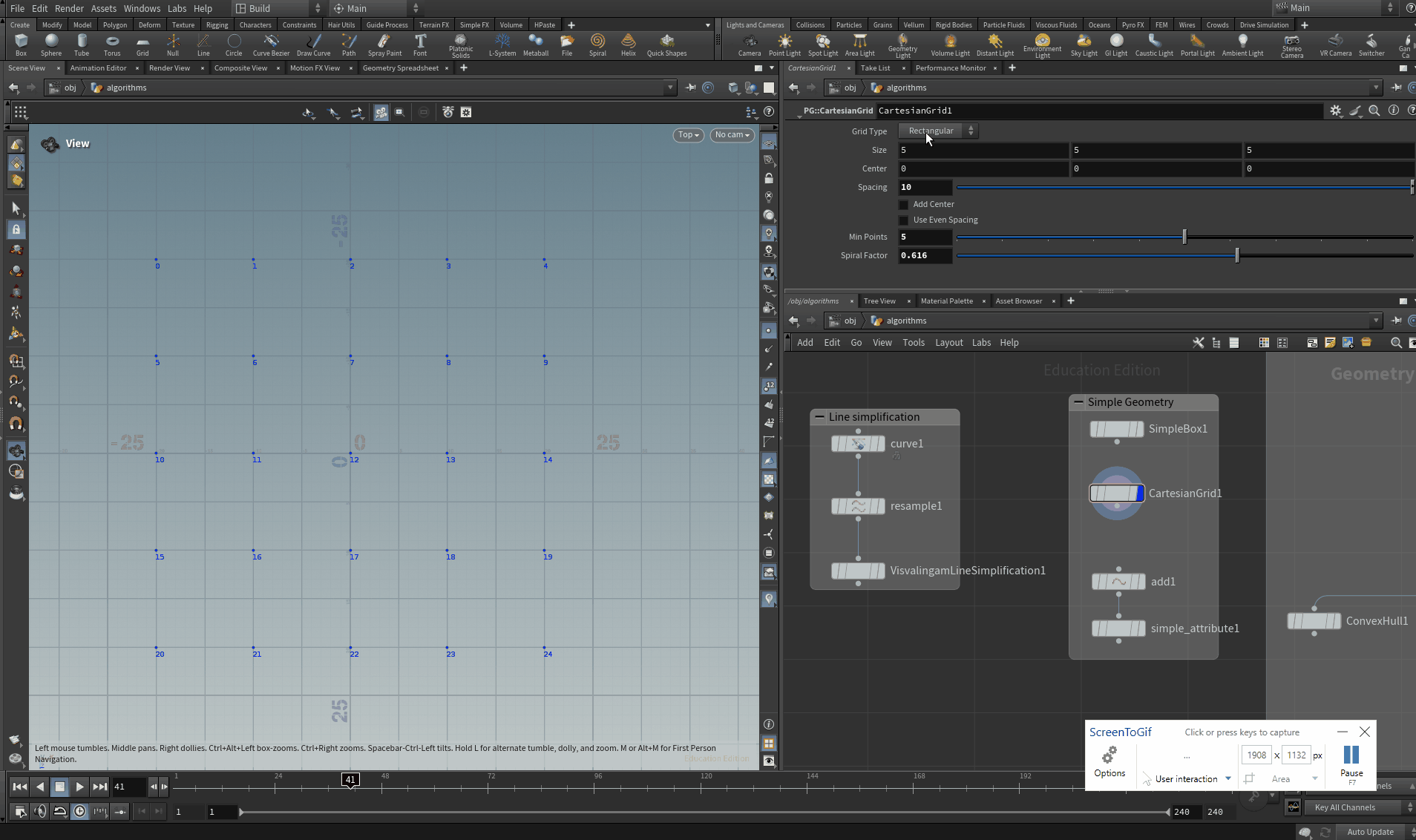
Cartesian Point Grids
This node creates points in the order of a few cartesian grids. It was my attempt at implementing more involved logic that requires more organization and a more involved interface. My focus was on splitting logic into functions where applicable and sharing data where relevant.
At this point, it becomes important to start to get familiar with the common Houdini-specific data types as most functions from the hdk will require them. This talk gives some insight into why Houdini C++ is written the way it is and hints at the usefulness of these data types.
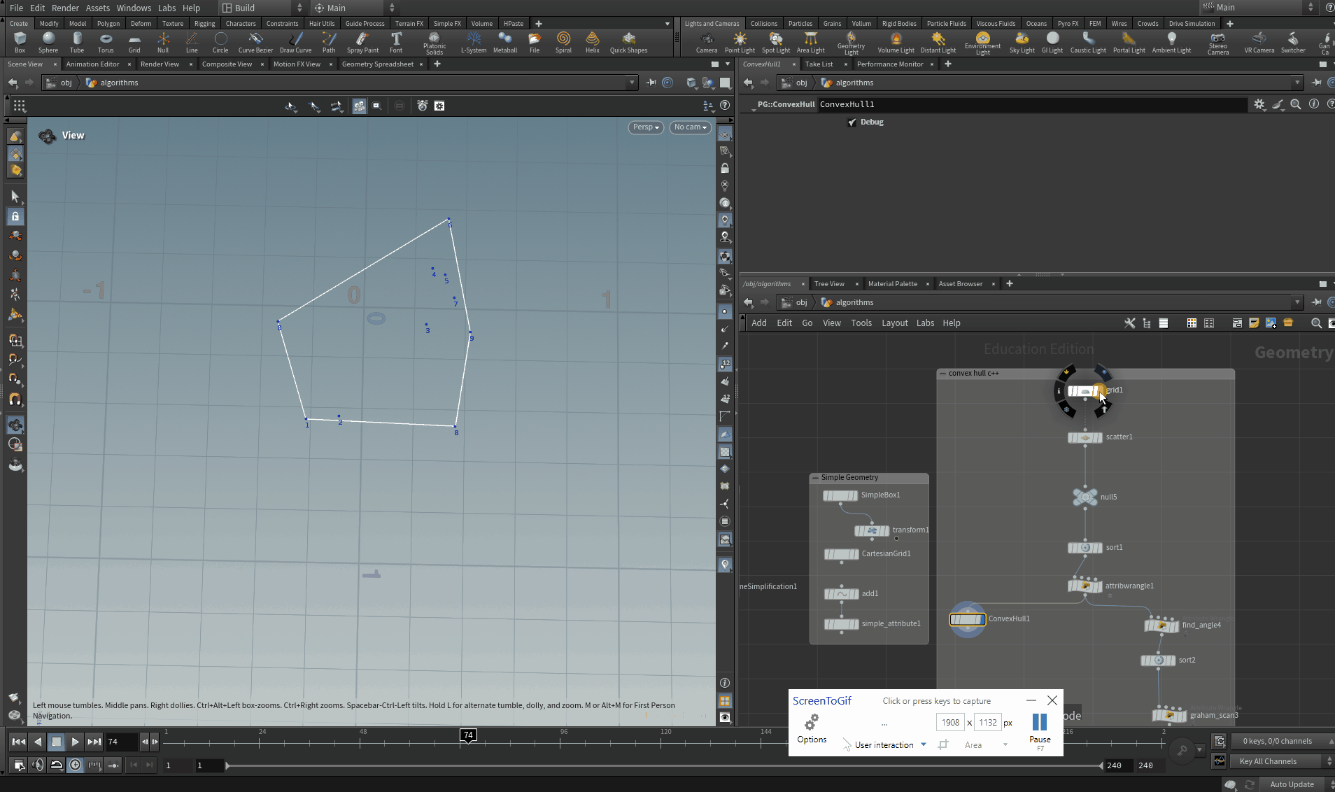
2D Convex Hull
Convex Hull is functionality already native to Houdini yet I want to practice implementing an algorithm that iterates over points, as this is another common operation with procedural geometry. My node uses the Graham Scan version of the algorithm. The HDK uses the framework of offsets and indices to help you track which points you are currently iterating over. In the example documentation, SideFX suggests using a GA_Iterator to loop through points.
For this algorithm, I used a struct to store the point offset and angles to access later on in the helper function that checks if a point is clockwise or not. My biggest issue when developing this node was updating the viewport. You need to explicitly update references to any data you have modified on your geo. This page on the Houdini documentation explains why and how. I also made a forum post addressing this. The simple thing to remember is to bump all data ids.
Line Simplification
This node is an example of functionality that you can achieve with a few wrangles and vex. Yet at scale, it could benefit from being very fast. I borrowed the logic from this implementation. It solves the points to cull when simplifying any line by finding the cumulative area of triangles formed between successions of three points. Since we are taking an input and modifying its content it is important here, as well,l to bump all data ids to ensure the viewport updates when points are culled. The source code includes the vex implementation as well, if you are curious.

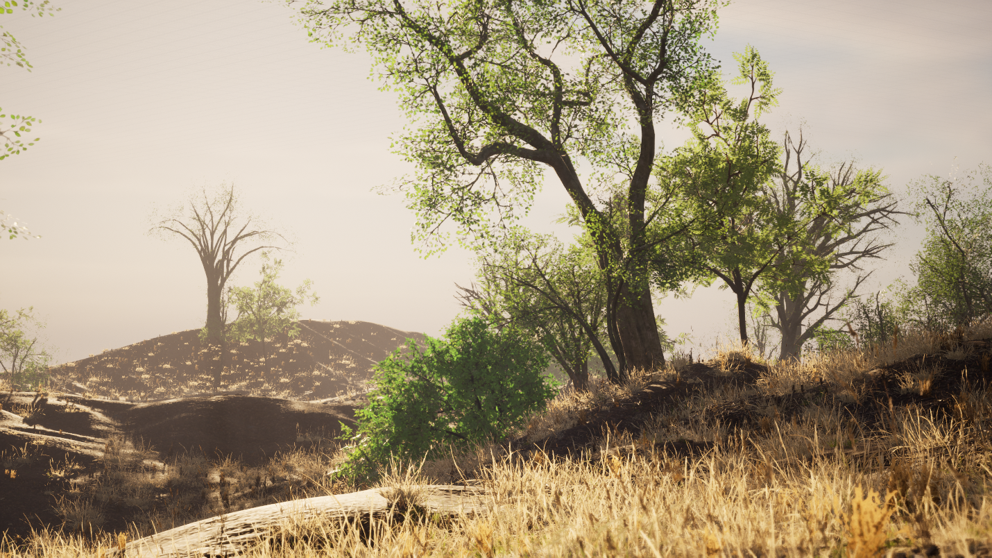
Procedural Biome Authoring Using Relational Data Models In Houdini for Unreal Engine 5.2
In this third blog post on procedural biomes, I will discuss my approach to designing a procedural biome authoring system that relies on a relational database model. I will discuss a suite of tools developed with Houdini as Digital Assets for Unreal Engine. The main focus of this blog post is the methods for deriving positional data for different biomes actors, such that each environment's visual specificities can be art directed consistently. This is a research-intensive subject and will focus solely on the broad strokes of encoding and decoding positional data and implementing that data in a hierarchical instancing system. We stand on the shoulders of Giants. This approach is inspired by this talk by Paul Ambrosiussen. My approach diverges from his by relying on relational data models described as 2D images and CSV files.
Overview - Biomes as Archetypes
In this context, I will use the term biome to refer to an ecological/biogeographical subunit, identifiable by various dynamic relations between actors in that subunit. Biome will also be used in a more abstract sense to describe a predefined hierarchical relationship that exists between assets placed in a 3D environment.
Replicating the visual consistency and chaos of natural biomes procedurally is especially difficult to achieve in a purely randomized or data-agnostic system. Leveraging ecological data on the various components that compose an environment such as vegetation density, climatic or geological factors, soil types, etc, can serve as a point of orientation in providing precision and control for a procedural system. Such data, although available, can be quite difficult to organize in some relational manner.
The suite of tools to be discussed in this blog post are an example of various strategies for managing relational data associated with biomes. They are designed to be used on an existing landscape in Unreal Engine and provide an artist with a set of simulated archetypes that drive the instancing of foliage and other actors composing an environment.
This example focuses on four of the fourteen natural biome types(excluding aquatic biomes). I will discuss parts of the technical implementation, specifically, data encoding and decoding and general tips for managing dynamic data. Finally, I will share a few test results of the tool in use and the user interface.
My explicit goals were as follows:
Abstracting vegetation features into biome archetypes
Designing data encoders and decoders for 2D and relational databases
Managing dynamic data between Houdini and Unreal Engine


Technical Implementation in Houdini
Designing a Data Encoder
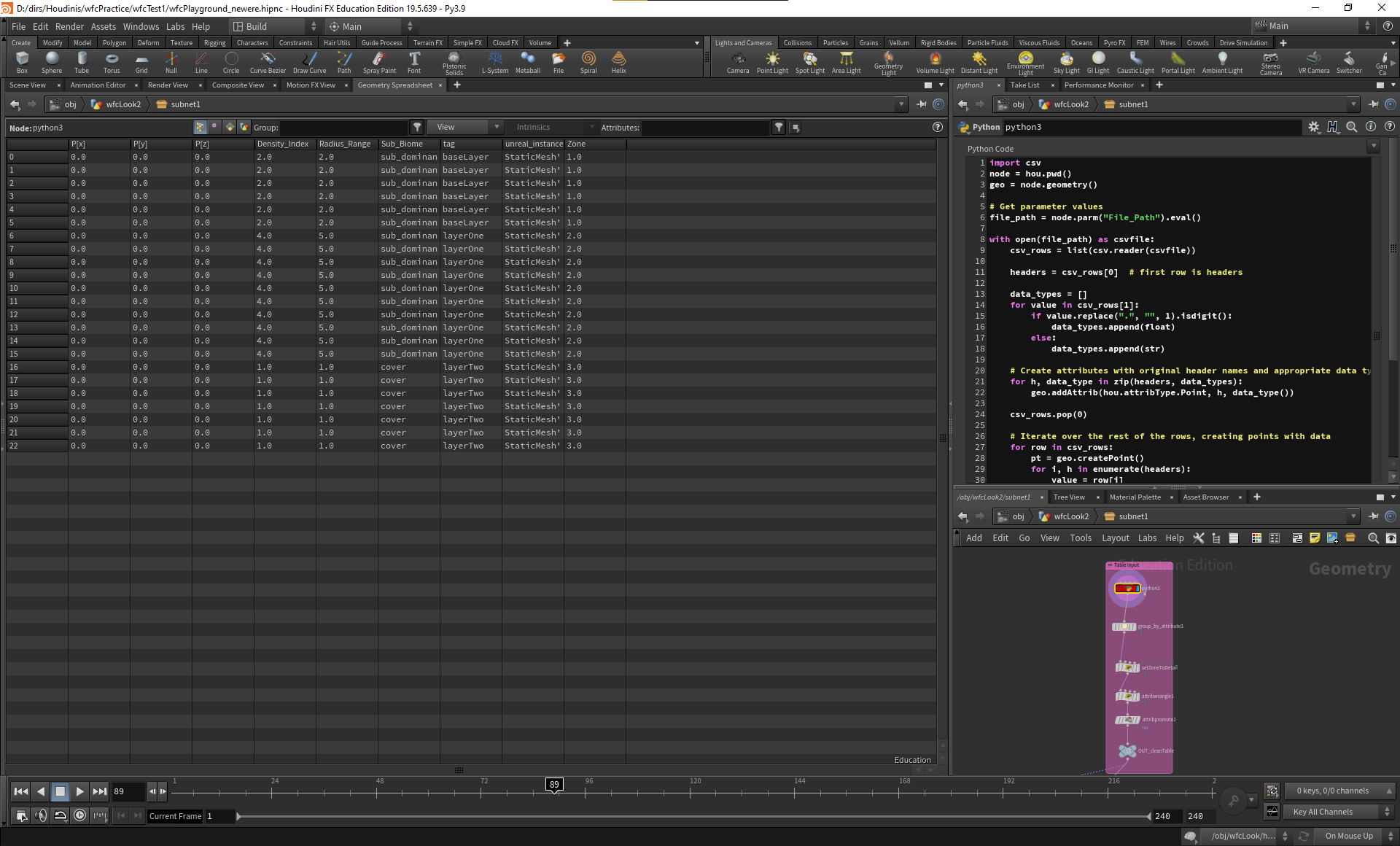
After completing the requisite research for this tool I created eight different biome archetypes as CSV files that included the relational attribute such as sub-biomes and density indexes needed. Each Archetype is also defined as a 2D image with different colour channels used to encode the density and sub-biome attribute we need. Some of our data, such as asset paths, for example, is useful when stored in string format in a data table and other data is easier to decode as pixel colours, justifying the use of two different data pipelines
Using Python to Decode Database
The next step in the process is to use Python to bring our custom 2D maps and CSV files into our Houdini environment. Whilst Houdini’s native Table Import Surface Operator is oftentimes okay, for this tool it was better to write my own Python function to handle the data I had. This is mainly to streamline the creation of the attributes we need as well as alleviate some of the problems of dealing with dynamic data between Houdini Engine and Unreal Engine.


Research and Design - Developing Biome Archetypes
To begin this project, I collected as much data as I could on the fourteen biomes we have on earth, particularly interested in their geographical distribution, climatic factors, vegetation density and also proximity to water. These factors and many more are key attributes that define the visual and experiential features of the environment. Being able to organize these attributes with some relation to our assets will allow us to define the archetype of each biome.
An archetype, in reference to an environmental biome, refers to the most typical example of that environment. Most coniferous forests for example have a dense and closely packed primary cover zone, bounded by a tertiary layer of grassy field. A subtropical rainforest archetype conversely consists of three layers of canopy cover.
In this demo, we will use research data from the WWF to produce biome archetypes for four biomes as 2D image maps that describe the interaction between various sub-biomes as well as the vegetation density of each zone. The graphic below describes a simplified approach to achieving this.
In the next section, I will discuss how we can then exploit Houdini's amazing suite of simulation tools to recreate similar archetypes that will match the original environment we are attempting to recreate by encoding and decoding these biome archetypes.
Simulating Sub Biome Interaction Using Wave Function Collapse
Wave Function Collapse is especially useful in this context, as it allows us to simulate interactions based on pattern recognition. Natural biomes, despite their beautiful chaotic nature, can generally be reduced to repeatable patterns. In this context, we will be using our biome archetypes as source patterns and supplying interaction rules to the algorithm. This allows us to seed variations of the original biome that still adhere to the rules of the specific environment.
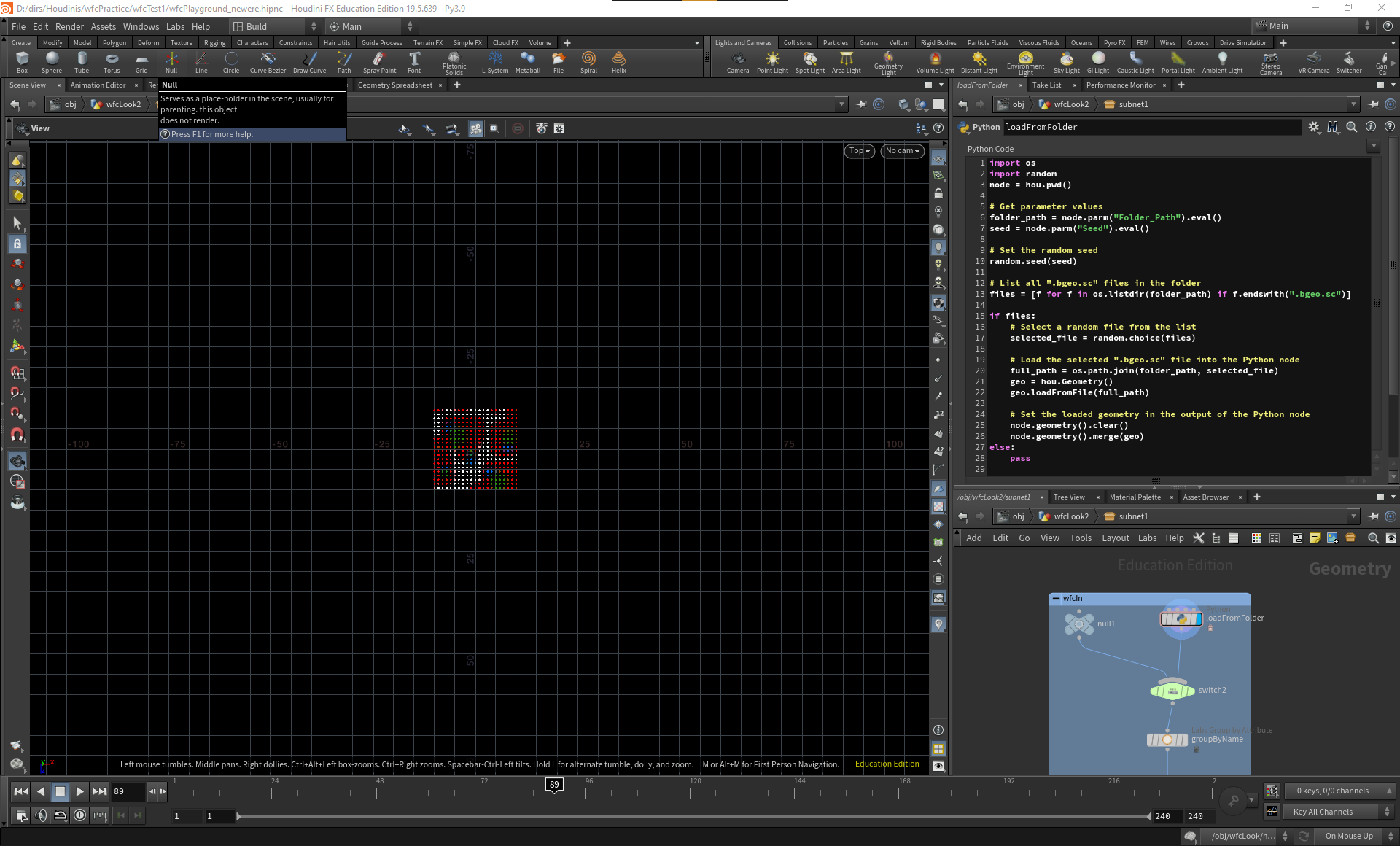
In this example project, I used Houdini’s Procedural Dependency Graph to simulate a number of biome interactions and then selected the most interesting as a biome style sheet. These style sheets are stored in a local cache and dynamically loaded into the main instancing tool. PDG allows you to curate randomosity in interesting ways. In a follow-up blog post, I will go in-depth into the exact biome interactions we simulate. The results are exported out as “bgeo.sc” files including our key attributes encoded on the colour channel of each pixel
Decoding data for hierarchical scattering
Now that we have simulated our biome archetype, we can then implement them in a hierarchical instancing system to generate the environment in Unreal. Here again, our archetype attributes are related to each layer/zone hierarchically. This allows us to change the relationships between each zone simply by switching the database, as the density attribute will be transferred. This section is responsible for how you derive variety from your archetypes.


Implementation in Unreal Engine
In Unreal, the instancing tool takes a landscape as an input. The user is able to select different biome archetypes which are then instanced to match the needed environment, including, foliage, ground cover and rocks. The user has control over a few placement options of the entire biome and per zone. The current examples demonstrated in this blog post use a limited set of assets available for free from Quixel/Epic Game


Expansions and Performance Optimization
As highlighted in my previous blog post on procedural biomes, there is still the issue of dynamic data. We do have to be aware of when certain data should be available in the system when it is made available and what will happen should it be unavailable. For this demo, this is handled by caching all relevant data and a number of validation checks to minimise crashing
Currently, there is also a problem with the “2dWaveFunctionCollapse” Surface Operator in Houdini. I have reported a bug and perhaps in the future it will work in Unreal, but my current solution is to cache the result of the simulation in a local database and load only when needed.
The instancing tool on its own, is not so computationally expensive as most of the cost comes from performing analysis on the incoming terrain from Unreal. To mitigate this and make the tool faster, you could use pre-generated terrain maps, rather than loading the heightfield into Houdini via session sync. Houdini is still far superior in generating the kind of vegetation-specific maps you will need, as you can simulate water level and sediment trails, useful for defining the specific placement of rock for example. Pre-baked height maps would be useful should you already have roads or settlements laid out that you would want to avoid in a natural environment. This will also be completely different if you are dealing with real-world data as the bases of your landscape. Scaling for example would be something you would have to consider.

Credits
Assets Used:
Quixel Megascans Foliage - Epic Games
Data-Driven Instancing Using Relational Models - Procedural Biomes with Houdini for Unreal Engine 5.2
In this second blog post on procedural biome generation, I will discuss my research and technical approach to developing a data-driven instancer. I will reference a Houdini Digital Asset for Unreal Engine 5.2 that uses relational data to instance large asset libraries.
Overview - Biomes as Data tables
Biomes, as some spatial units, can be approached from the point of view of data analysis when designing procedural generation systems. In 3D worlds specifically, most biomes can be specified by relationships between assets, like the tree to the grass, and the rock to the path. However, biomes often require the artist, technical or otherwise, to manage complex relationships in data that can quickly spiral and regress towards a statistical means leading to a repetitive unnatural distribution.
However, exploiting the explicit relationships in whatever data comprises your biomes, can be an elegant way of expressing control and precision over how and where different assets in your biome are placed.
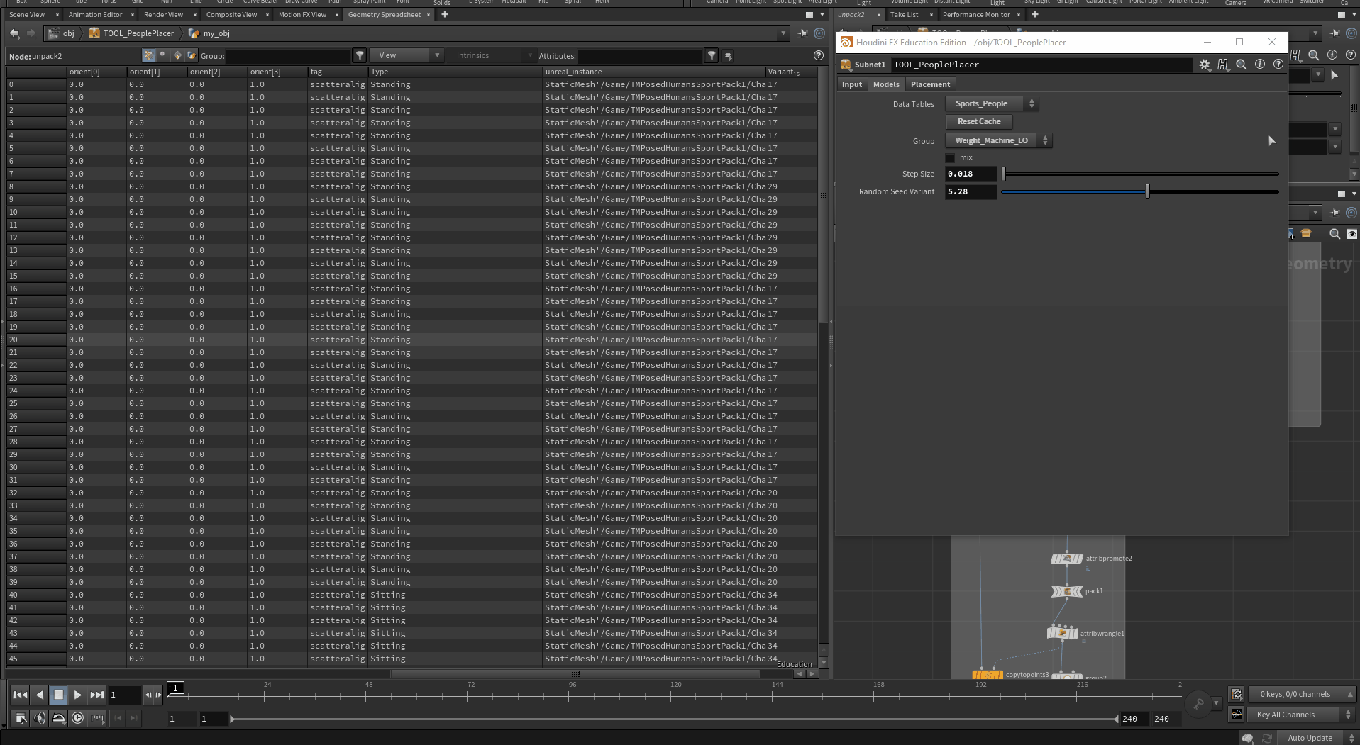
To demonstrate how such a procedural generation system could work, I designed a data-driven instancer in Houdini for Unreal Engine. It takes an input of data tables/CSV files with predefined categories of assets (Static Meshes and Blueprints) and allows an artist to procedurally instance any group of assets in a hand-drawn space. Such a tool could be useful especially for interior spaces, as in the example of a gym, an office or a restaurant. You can quickly iterate over categorised assets libraries that comprise these spaces to art-direct the look you require.
My explicit goals were as follows:
Data-driven instancing - using relational data to drive instancing
Categorizing and managing assets libraries in procedural systems
Artist friendly and computationally inexpensive
The above video demonstrates both the technical and practical application of the tool in Unreal Engine 5.2. In the next section, I will expand on the technical implementation of such a design system.


Conceptual Approach - Exploiting Relational Data Models
This method of biome design relies on a relational data model, where assets are grouped into banks/categories of assets, expressing logical links that establish high-order patterns. These categories or patterns are easier to manage and pair nicely with dynamic systems. The task of the procedural biome tool then becomes about giving the artist precision of control over the categories predefined in the datasets. In the example tool, the key data we are interested in are the area of each asset as well as their categories and file paths. Our user interface will abstract the various operations we perform on this data for the artist to control. This design approach takes a lot of planning and data management however it pays off in the long run.
User Interface
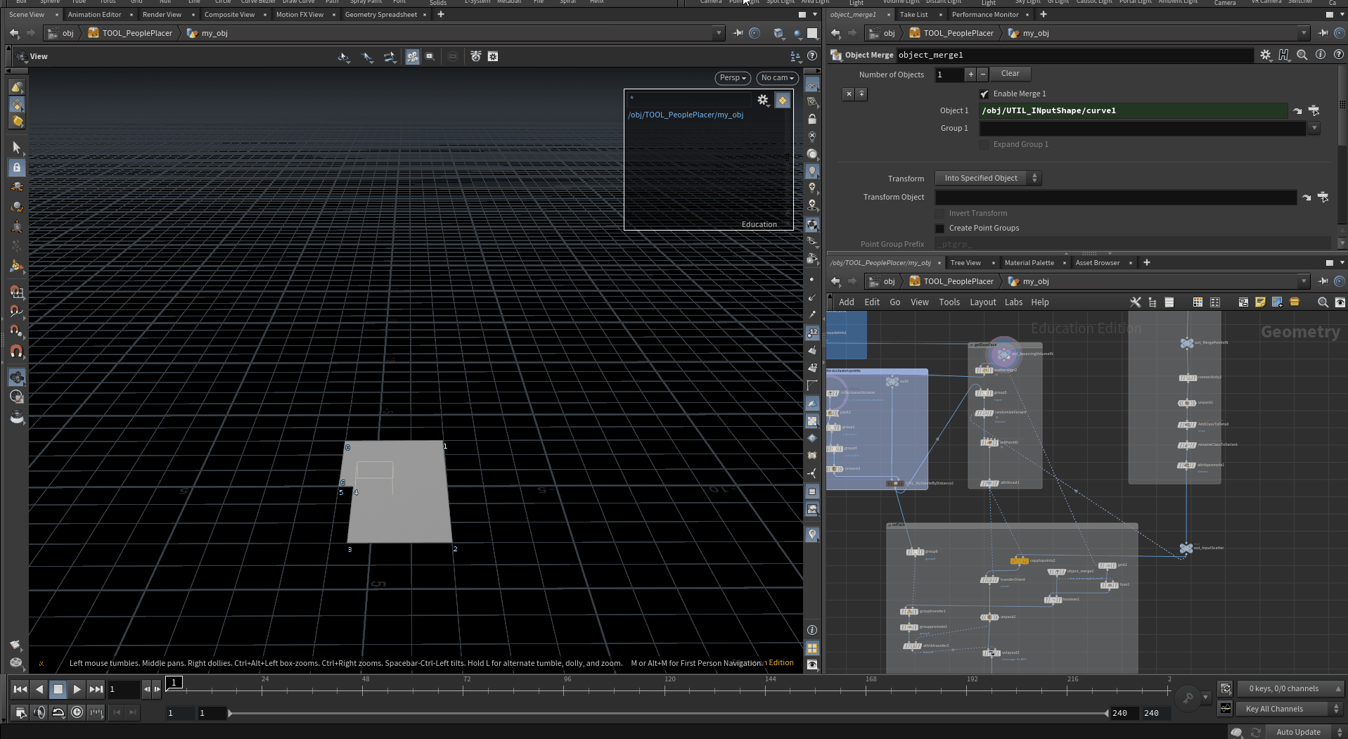
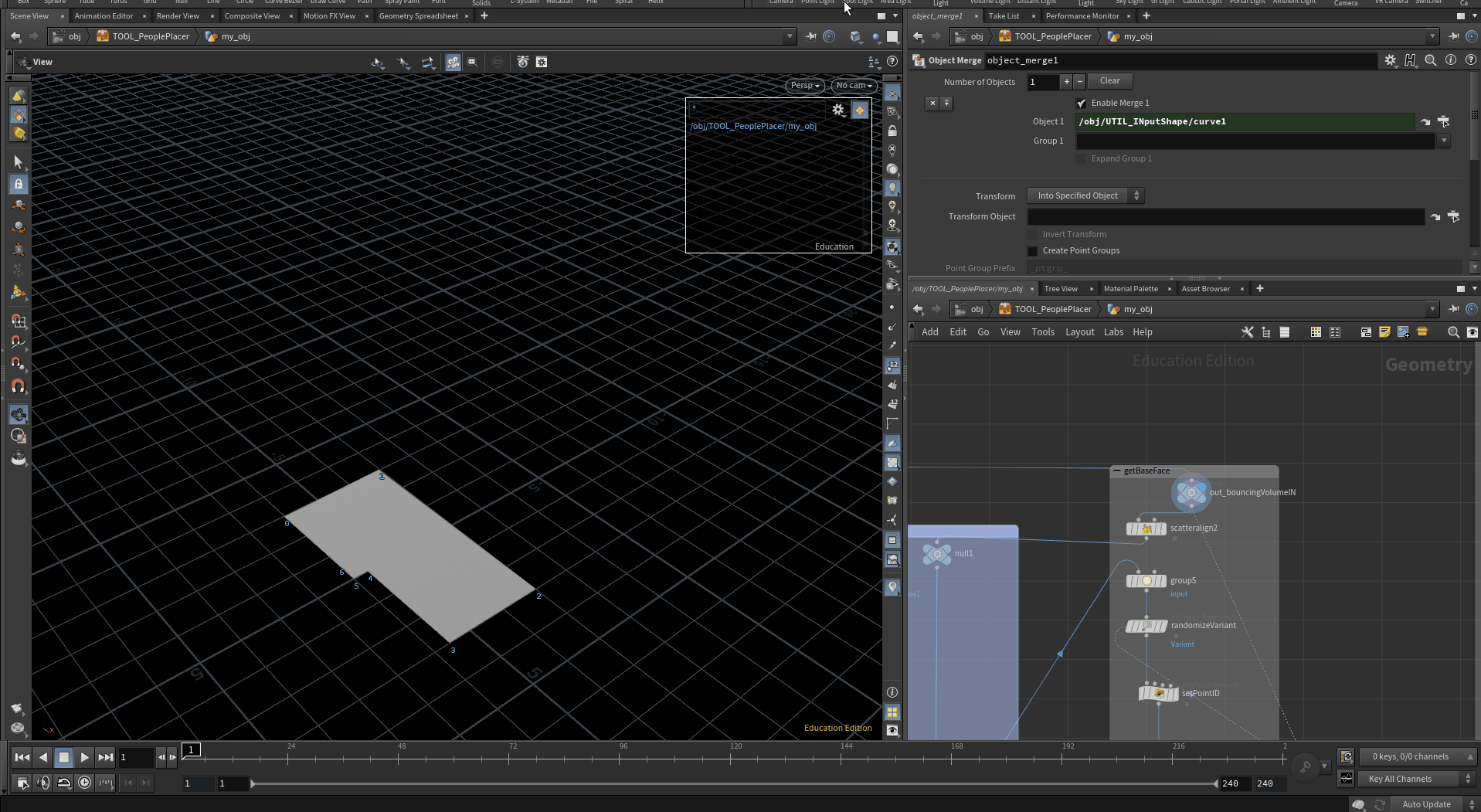
The main function of the interface is to help the artist manage large assets libraries with just a few menu options. It is divided into 3 main sections, each for one of the main functional parts of the tool. The user is able to define an area to instance asset using an input curve. They can then decide on which category or subcategory to instance in whatever spatial pattern they want, adjusting destiny, orientations, scale, etc, for more natural distribution. Additionally, the artist can occlude the instances from certain parts of the environment by selecting the occlusion volume. They can also instance on non-flat surfaces by selecting the asset they want to use as a floor.


Technical Implementation
This tool builds upon the use of UV packing in the Stack Tool demonstrated by Side FX in the Project Titan Stacking Tool by Thomas Tobin. My implementation branches and includes relational data tables and other features explained below. I also received assistance from Quentin Nédélec and Erwin Heyms via Discord.
Dynamic Relational Data Tables
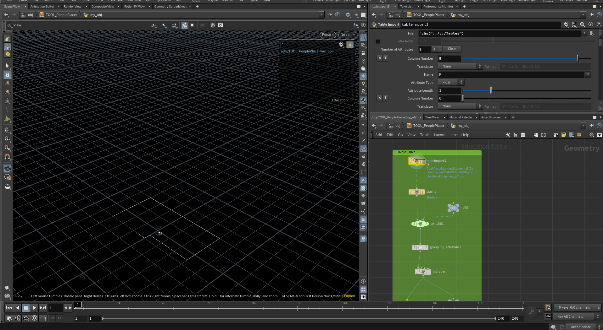
This tool makes use of asset libraries provided by Epic Games. The first task is to manually create the relational data tables you need. This can be done in Unreal Engine or any CSV editor. In Houdini, this data is importable via the Table Import Surface Operator connected to a menu with a list of the paths of the data tables.
Aside from the time investments and concentration needed to prepare the data, there are a few things to be aware of when trying to use dynamic data in a procedural system. Here we decide to manually recache the data table, each time a new one is loaded into our code. This prevents any crashing should any interface options request data before it is loaded into our system. There might be better ways of handling this, but for now, i found manually re-caching to be the most stable way of dealing with dynamic data between Houdini and Unreal. I welcome any suggestions.
UV Packing
The next step is to determine how to pack the points within the user-defined space. Houdini’s UV Layout Surface Operator is flexible enough to be used to pack data that is not UVs. Here we use it to pack the instances from our data table based on the area of each instance. Combining this with other standard scatter techniques yields efficient and precise instancing with a lot of control.
Occlusion By Distance
Occlusion is a useful feature to have in any procedural instancer. We use a custom subsystem to prevent instances from appearing inside assets that might already be in the environment. We sample an occlusion volume, using only its low poly footprint to prevent inputting heavy meshes into our system. We can then delete points/instances should they overlap this occlusion footprint. This works in real-time via Houdini Engine Session Sync.
Finding The Floor via Raycasting
The final section of this tool is a sub-system that allows the user to define a floor of surface to sample to align the instances to. The tool only accounts for the surfaces perpendicular to the ground plane. However, we might have some horizontal variation on the plane. To solve this, we ray-cast the points onto the selected floor surface. The key thing to remember is to always have your points above the ground, before ray casting so they always maintain the orientation.


Conclusion
A possible improvement to the tool would be an auxiliary tool to sample the input space and provide polygon curves to determine where each category of instances should be placed. This would diverge from a conceptual approach that would slightly de-emphases the utility of the artist in creating a biome.
However, in this current iteration, as the data table input is dynamic, the tool can be extended for any kind of workflow that might require the use of relational asset libraries.


Credits
Assets Used:
Test Room - Epic Games
Big Office - 1D.STUDIO
MEDA Furniture Pack - Renderlogic
Loft Office (Modular) - Next Level 3D
Twinmotion Chairs & Tables Pack 1 - Epic Games
Twinmotion Decoration Pack 1 - Epic Games
Twinmotion High Tech Pack 1 - Epic Games
Twinmotion Posed Humans 1 - Epic Games
Twinmotion Posed Humans Children Pack 1 - Epic Games
Twinmotion Posed Humans Shopping Pack 1 - Epic Games
Twinmotion Posed Humans Sport Pack 1 - Epic Games
Twinmotion Posed Humans Winter Pack 1 - Epic Games
Twinmotion Sports Equipment Pack 2 - Epic Game
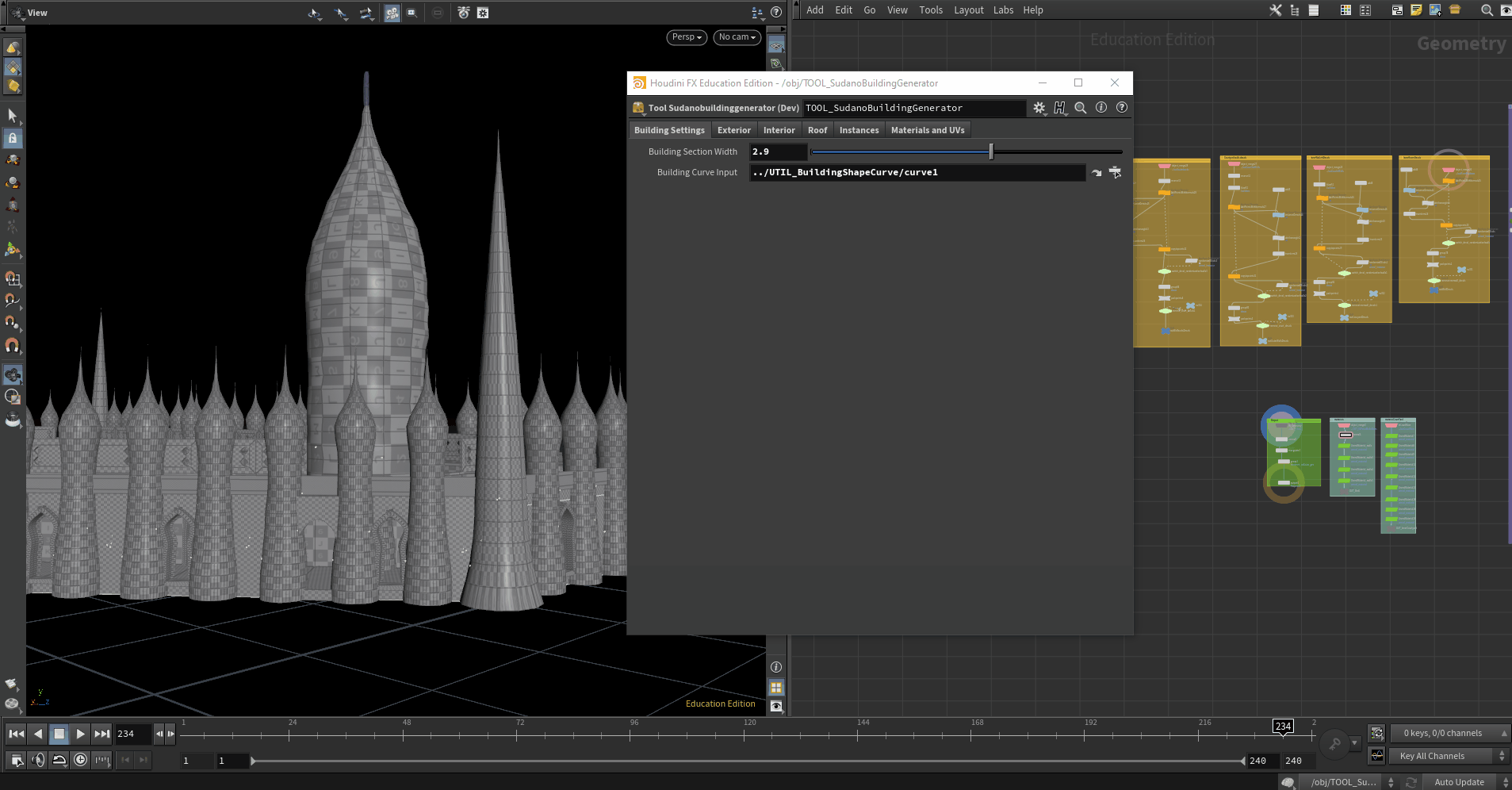
Sudano-Sahelian Building Generator - A Houdini Digital Asset for Unreal Engine 5.2
In this technical blog, I review my design choices and technical approach to producing a Houdini Digital Asset for Unreal Engine 5.2 that allows an artist to design and model a Sudano-Sahelian traditional mosque procedurally. This blog post is split into sections; the first is a general overview summarizing my motivations. The next section details my research insights, design system and the technical development of the tool, the user interface as well as performance optimization. The final section reviews some technical hitches encountered as well as insight into practical use cases of the tool.
Overview - Procedural approaches to traditional buildings.
Despite the ubiquity of procedural building generators, few of them focus on traditional or non-European architecture. I decided to design a Houdini digital asset that would enable artists to produce a unique Sudano-Sahelian mosque with a high degree of art direct-ability.
I focus on this style of West African buildings as their shape grammar is consistent and symmetrical. Yet they combine traditional and borrowed building techniques and materials such as reinforced pillars, stylized walls, symmetrical patterns and open entryways which lends each of them a unique stance over the surrounding landscape.
The resulting tool is expected to produce traversable buildings with collisions and materials configured whilst having a minimal polygon footprint, capable of being replicated on the scale of a small city.
My explicit goals were as follows:
Visual variety - different regional building styles from the same tool
Controlled randomness - precision over instanced meshes and decals.
Consistent Organic Forms - arches and pillars
Design system implementation - researching and configuring a design system as a Houdini Digital Asset for Unreal Engine.
The above video shows the tool in use in Unreal Engine 5.2. In the following sections of this post, I detail some of the steps taken to achieve this result


Research - Patterns and Buildings as Biomes
Sudano-Sahelian architecture is prevalent across the Sahara desert. I am familiar with this style of building from Northern Ghana, with The Larabanga Mosque built in 1421 being one of the oldest buildings in the country. I collected images of different Sudano-Sahelian Mosques I wanted to replicate in my tool. This is important for understanding the patterns that combine to complete the shape grammar of whatever form you want to model. As they are most are religious buildings, they are usually symmetrical. Yet, each is quite bespoke with careful detailing embellishing the basic shell of the building.
Also key in the research phase was finding a diagram that shows the interior design of these buildings. Most photographs are of their exteriors and I was lucky to find one that showed a plan view, revealing the organization of internal walls to create rooms and corridors. The research phase for me establishes the scope of the tool, helping me figure out how to approach modelling. It was evident that I would have to treat this building as a sort of biome, similar to the development of my previous tool, where related sections define the connection as a whole


Interface
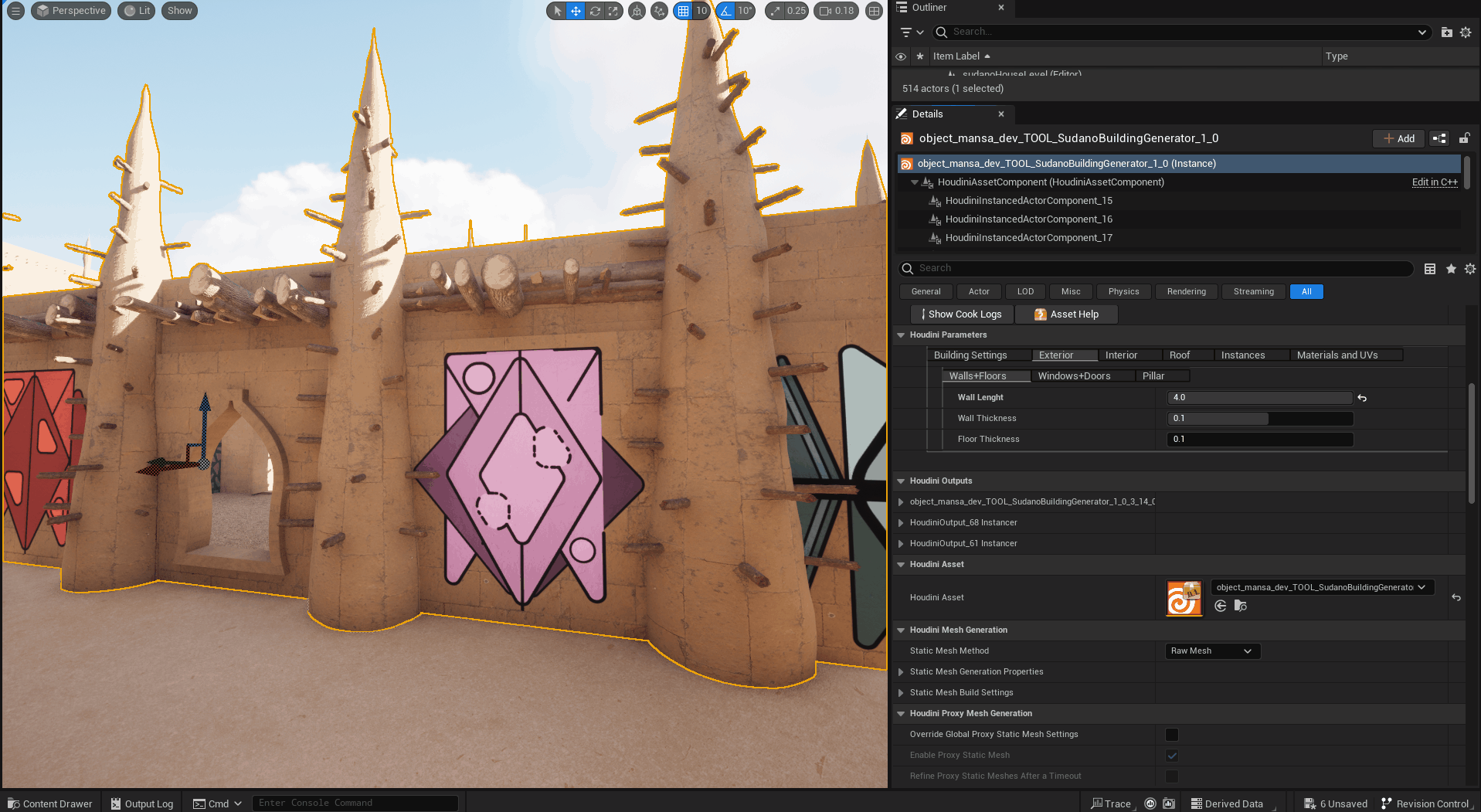
The intentions of the interface are to allow for easy customization of a familiar form. Users should intuitively design each section of the building in a coherent design language and customize it to fit a specified art direction. The tool is controlled by a series of sub-menus for each major section of the building. After inputting a curve for the footprint of the building, the artist can then adjust the placement of pillars, rooms, the courtyard and stairs by adjusting value ranges. The user interface also allows for configuring materials and instancing wooden support beams and decals on the walls.

Technical Implementation
I discuss a few technical decisions that are key to meeting the goals of the tool, rather than explaining each section of the Houdini Graph in general. My tool builds upon techniques developed whilst attending this foundation course by Erwin Heyms on procedural modelling for Houdini which is free and I highly recommend.
Consistent “Organic” Geometry
The digital asset began in Houdini with a similar waterfall approach I have used in previous procedural modelling exercises. Related sections of the building are treated independently and combined at the end of the chain. One key thing to consider was accounting for non-uniform geometry. Such buildings in real life, due to the materials and technique used, lack a consistently even surface. Their walls are usually bumpy and uneven.
However, when working procedurally, it is important to always have clean or consistent geometry. This helps not only in configuring collisions and UVs for materials but also allows you to have a reliable tool that will produce consistent results in the hands of the artist. Although Houdini provided an extensive toolset for modelling non-uniform geometry such as Volume Modeling with VDBs, I decided against this approach as it would be computationally expensive for the scope of the generator.
Rather I decided to use curves revolved around the vertical axes. I have explained this technique in detail in my post on modelling a flower pot. Here, the revolved forms are augmented with a bit of noise for consistent yet organic-looking pillars, arches and minarets, all key components of the “look” of the building. This technique is also particularly easy to extend into an interface as the user can iterate on form by moving points on a curve that represents the cross-section of a door or window arch.


Controlling Large Amounts of instances
Another major technical hurdle to address in designing this tool was how to handle a large number of instances. The load-bearing pillars of these traditional mosques are supported by wooden beams and boards. I decided to use instanced static meshes for the support beams rather than modelling them, to reduce the computational complexity of the tool. Thus, I would have to come up with a system to manage assigning instances to the correct points on any desired surface of the building. As with the walls themselves, a careful approach to randomness is essential to have a non-uniform distribution that looks unique yet non-standard.
To solve this I have a small sub-system capable of initializing a grid of evenly-spaced points on any sized flat surface. I then parameterize various options such as scaling, orientation, etc to ensure a natural-looking pillar. This subsystem is then replicated on all the major parts of the tools, giving the user precise control. Developing this subsystem is particularly key to ensure that the tool can be art directed to produce a variety of Sudano-Sahelian styles, as the kind and placement of support beams is a key feature that differentiates these buildings from one another.

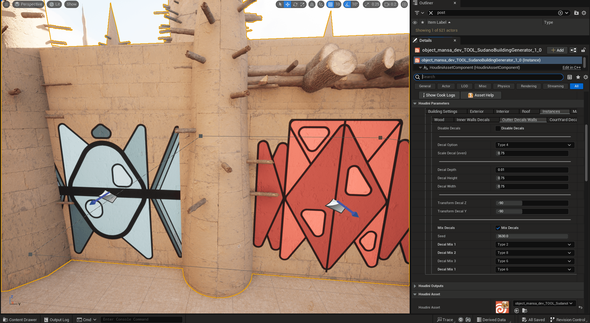
Decals
Apart from static meshes, the same subsystem also handles instancing decals on the surface of the wall. Perfecting this system probably took the most time, simply because of the clash between two different orientation systems. For reference, whenever you are instancing, remember to adhere to one orientation system.
When instancing decals for Unreal Engine, the Cross vector is the forward-facing direction of the decal. The Normal Vector is the downward-facing direction and the Up vector is the right-hand direction. If for some reason you have an orient-based transformation in your graph, pack those points before merging them with points using the normal as their orientations. You can also refer to this video for visual clarification of this.
Performance Cost Control
Since the buildings produced from the tool are supposed to be traversable in a game engine and also have a lightweight polygon footprint, I had to be mindful of the overall performance cost to ensure that the tool remains responsive. The key thing to remember here is to manage your groups and attributes so operations down the waterfall are lean and fast. Collisions are handled using the “rendered_collision_mesh” group. UVing handled on each section of the tool. Allowing the user to stylize the building with different preconfigured materials should they wish to.

Insights
One thing I enjoy about procedural design is being able to implement systems of your own design as interactable rules. In making this tool, I enjoyed the problem-solving involved in translating research into code in Houdini. I am increasingly understanding that procedural design/modelling is more about control than anything else. One thing I would do differently is to define the scope of the tool early on in the process.
In this case, I focused on what is the basic shell of the building. I am currently developing other related tools to augment the look of the buildings as they are already in use in an interactive experience currently in development.
Reference:
Materials used - Quixel Megascans
Instanced Meshes (logs and beams) - Quixel Megascans
Houdini 19.639 for Unreal Engine 5.2


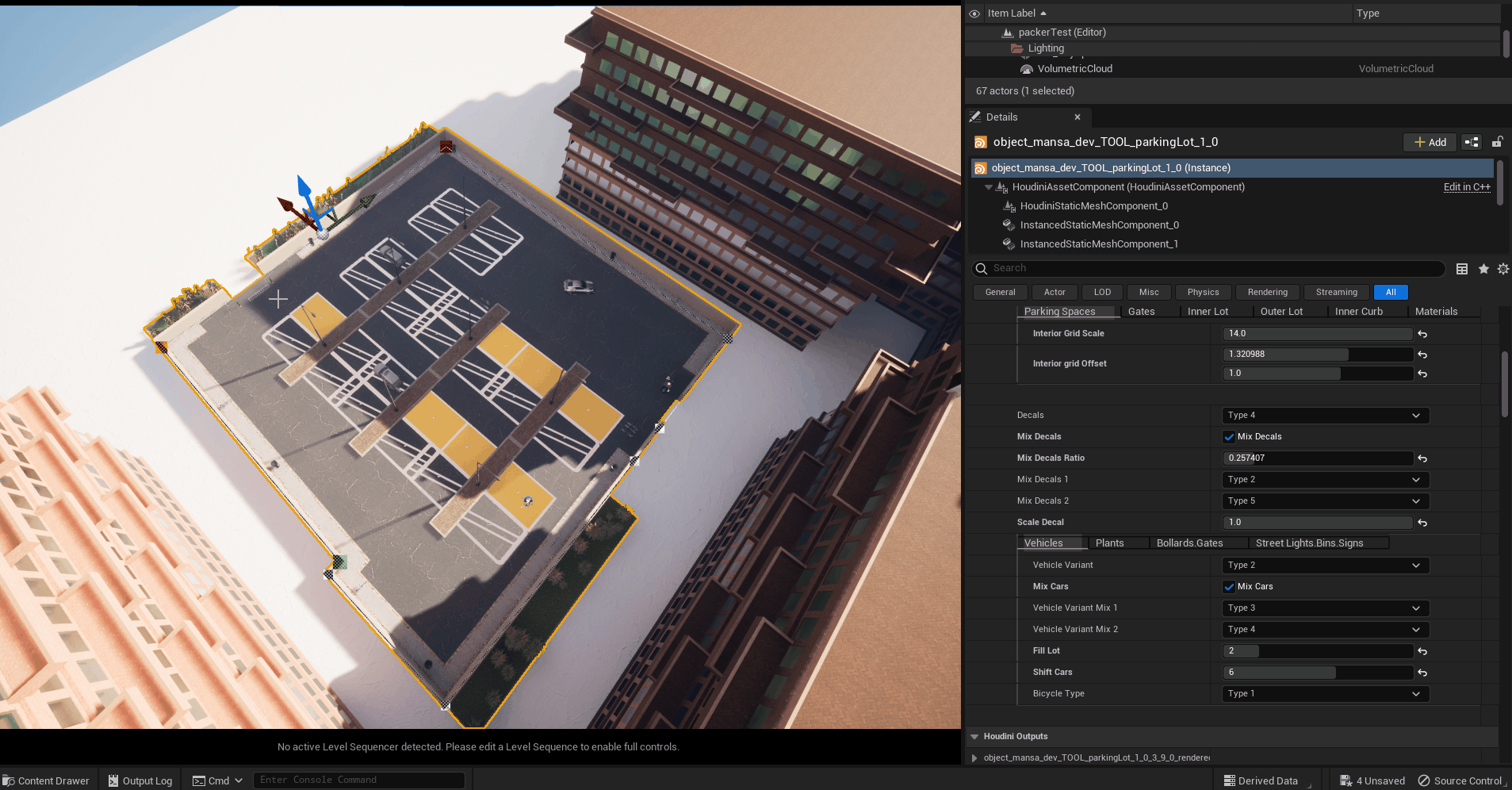
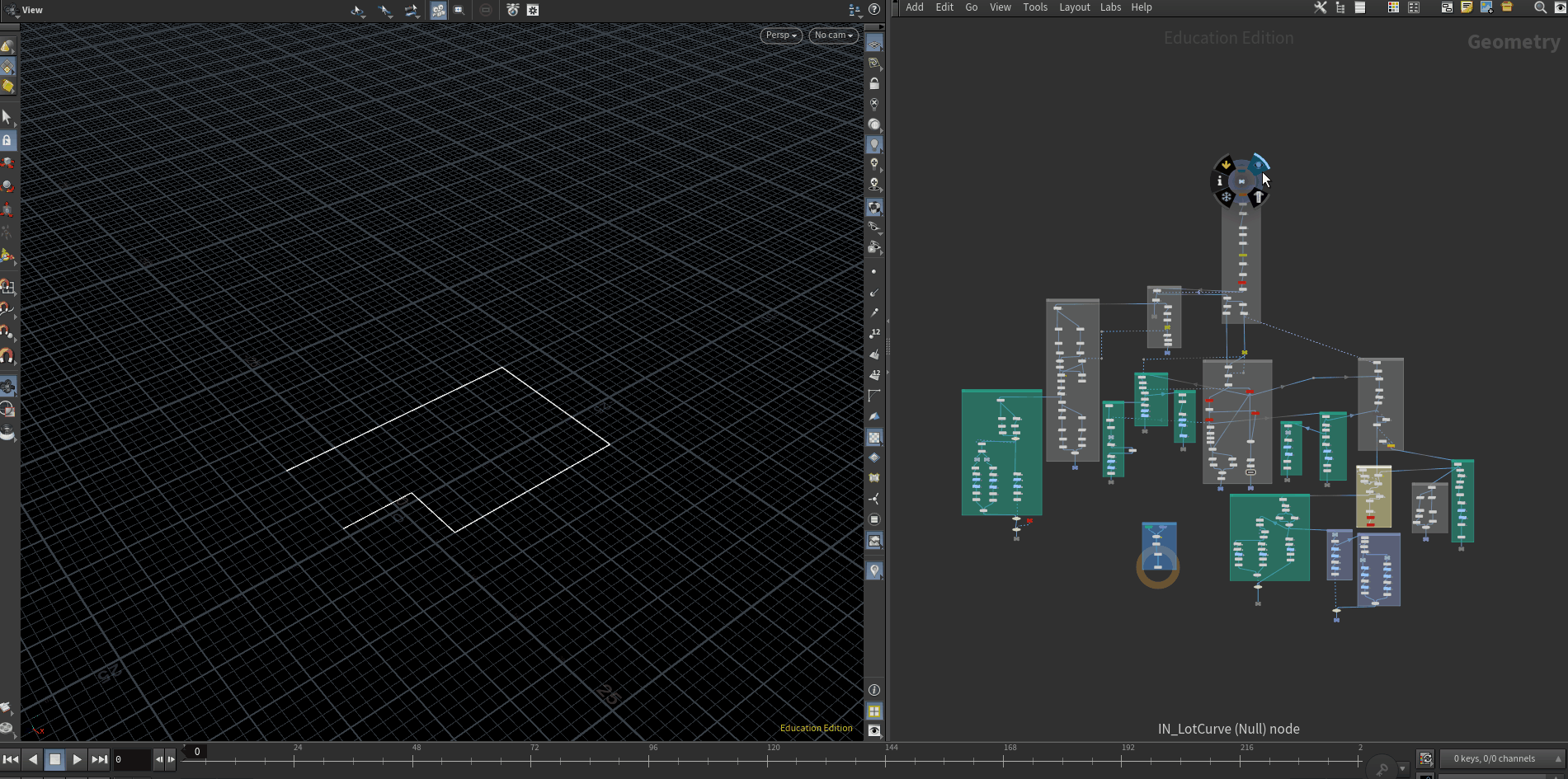
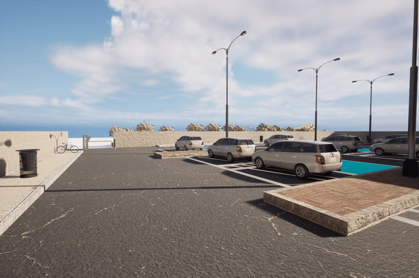
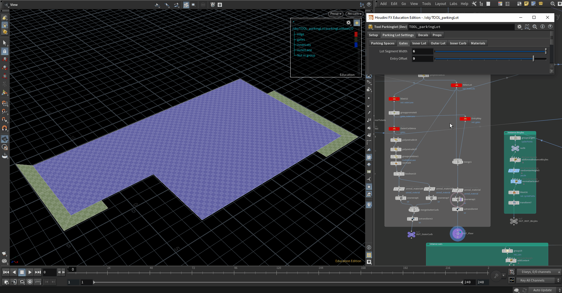
Procedural Biome Generation - Parking Lot Houdini Digital Asset for Unreal Engine
In this blog post, I will go over my design intentions and process for making a tool to generate an outdoor parking lot with Houdini for Unreal Engine 5.1. This blog post is split into sections, with the first addressing some conceptual considerations on procedural biomes. The next goes into detail on the technical implementation of this tool in Houdini. The final section gives an overview of the tool's implementation in engine.
Procedural Biomes - Design Intentions, Research and Planning
In the world of computer graphics, the term biome differs from its ecological application. A biome in a 3D or 2D screen space can refer to a specific environmental relationship that defines the look and function of a specific space. They form subsets of larger environments that establish a sense of immersion or believability. The main thing to remember about biomes is that they are identifiable by clear higher-order relationships. For example, a city block or a market square can be defined as a biome if you can aggregate some rules about how all elements in the environment relate to each other.
The rule-based nature of biomes means that they are an optimal conceptual approach for designing and managing procedural content generation. I wanted to practice my knowledge of procedural content with a smaller biome, in this case, an outdoor parking lot. All outdoor parking are functionally similar. However, they can be designed with a great degree of variability. To define a parking lot as a biome, the higher-order function I had to consider was the flow of vehicular traffic through the space. Cars and bikes would have to enter the park and exit in an orderly manner. This would then dictate the placement of gates, signs, bollards and lawns that together create a cohesive environment.
I wanted to design a tool that would allow an artist to draw in a parking lot to fit between some buildings. My reference for this came from outdoor parking lots in Germany and the Netherlands. My main goals were to practice the following:
Biomes as procedural content models
Instancing
User Interface Design
Rule-based group definitions
The resulting tool would allow a user to define a parking lot via an input curve and instance all relevant options. Via a multi-folder menu, the artist can replace assets, materials and texture to ensure visual variety and density. All instances should also stay within a rule system so no paths are blocked.
In the next section, I go over how I was able to achieve this in Houdini as a digital asset for Unreal Engine.
Technical Implementation - Houdini
In Houdini, that tool starts with an input curve that defines the surface and bounds of the parking lot. The road surface, lawns, cubs and paths are based on this input curve, ensuring that critical relational dimensions are passed along the graph. This works well as most of the modeling operations are performed on planar geometry. Here the main challenge was defining an order of priority, for example, it makes sense to model the exterior road that leads in and out of the parking lot, as this would result in a definition of the exterior wall and interior lots. Doing either of them before making the roads would have been more complex.
Geometry Groups
In order to ensure consistent hierarchical relationships between objects in the biome, I decided to take advantage of groups in Houdini for procedural modelling as well as instancing. One of the main technical challenges in designing this tool was to solve the problem of creating an interesting yet consistent geometry group. This is important to ensure that instanced meshes and decals for example have the correct scale and orientation and do not clip into each other. Solving this problem would also help in procedural UV unwrapping, ensuring that each mesh would have the correct texture scaling when edited in engine. I resorted to various range selection and group definitions in vex. Each group is then processed and merged at the end of the chain.
Instancing Static Meshes, Decals and other HDA’s
The next hurdle to tackle once I had all my geometry in order was instancing. Luckily regardless of the asset you are trying to instantiate, the process is quite similar, as all you have to do is assign the “unreal_instance” attribute to a point. The groups from the earlier stages would make this easy as I already had isolated surfaces and points to reference in instancing the streetlights, foliage or decals. You can refer to my previous blog post for more detail on how to achieve this.

Interface
Due to the sheer mass of data you have to manage when dealing with environment scale assets, I spent a lot of time refining the interface to ensure ease of use, visual variety and precision. Via three subfolders, the user is able to alter shape grammar, object position, types and other settings. I decided to configure dropdown menus referencing assets I would be using in Unreal. The artist still has control, yet the interface ensures that the tool produces consistent results.
Topology Optimization, Responsiveness and performance targets
I avoided using any loops and relied more on vex to ensure that the tool remained responsive. Although a lot of Houdini Surface Operators would suffice, I found that leveraging Spare Inputs and the Wrangle nodes led to lightweight computational complexity so the tool remained responsive. All typology is consistently planar and triangulated and unwrapped procedurally. This ensures that the tool also produces proper collisions and is traversable. Performance cost can increase depending on the complexity of the instanced meshes. In this example, all instances have LODs and work fine.

Insights and Next Steps
Considering this is my very first procedural biome, I am impressed by the precision and consistency of the tool, as seen in the video and the documentation I have shared in this blog post, the tool achieved my primary goal, which was to describe an environment through a series of related rules. The interface abstracts these rules into a user-friendly workflow that is still very customizable.
The main thing I would hope to improve is the management of instancing. I would consider using a data table in future iterations of the tool as finding and inputting references was the most time-consuming part of the development process of this tool. In my next blog post, I will share a project that further explores the design of procedural biomes. The parking lot is a man-made biome that is predictable. I would like to tackle more unpredictable natural biomes next.
Reference
City Park Environment Collection LITE - SilverTm
City Sample Vehicles, Epic Games - Epic Content
Quixel Megascans Surfaces + Foliage
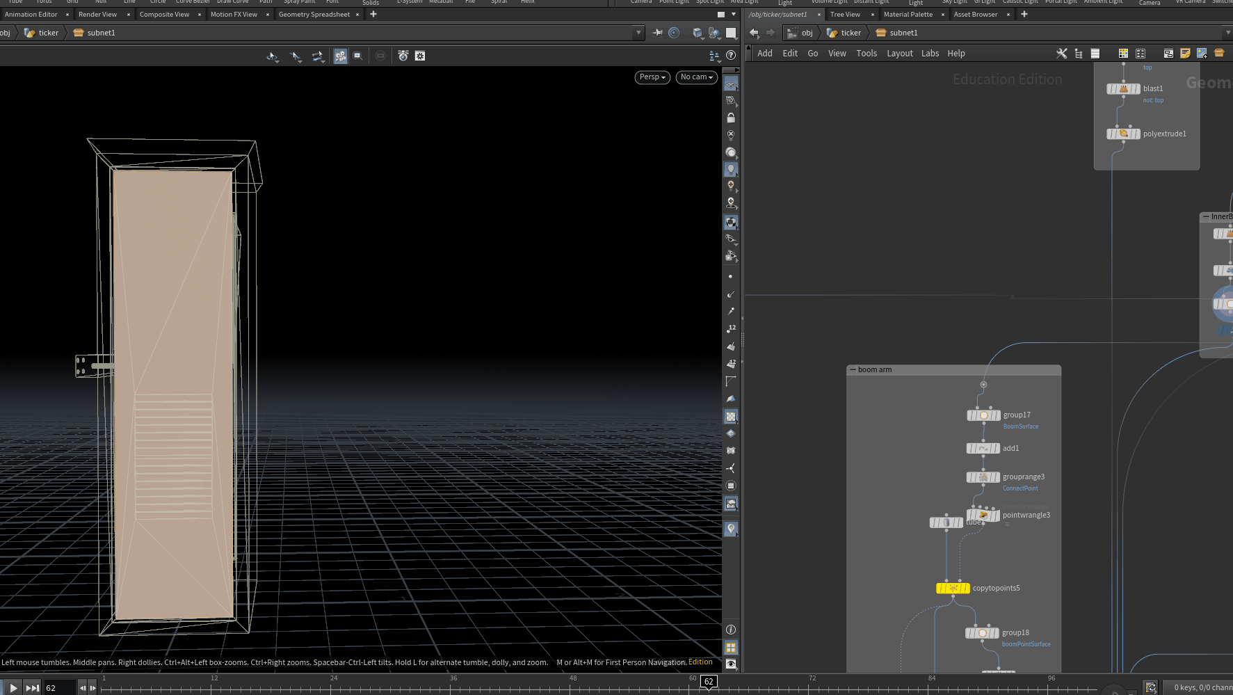
Procedural Modelling - Electronic Parking Gate System - Houdini x Unreal Engine 5
My next step in learning how to make procedural tools in Houdini from Unreal Engine was to design an asset for building an electronic parking gate system. Over the past few weeks, I have taken this foundation course by Erwin Heyms which goes into in-depth detail on a lot of the techniques and considerations for using Houdini for authoring procedural tools for game engines. The course is intently informative and I wanted to practice the knowledge I have learned from it. However, I decided to vary the challenge and define my own process for making the tool.
In this post, I want to go over the design and systems involved in making this tool. I will briefly expand on a few key concepts worth noting; for example how to instance Decal Actor from Houdini into Unreal, as well as other hard surface modeling techniques to ensure the tool produces clean topology consistently. You can watch the above video if you are interested in seeing the tool in action. I would also recommend the foundation course should you be interested in learning Houdini specifically for game assets.


The design brief of the project was to design both an electronic parking gate and console with one Houdini Digital asset for use in Unreal Engine. The assets produced from this tool should be able to slot into a realistic parking garage or city environment, along with the requisite textures and decals. The end user should be able to author both the gate with a boom arm, the street sign, and the console from the same tool.
The reference object is generic electronic parking systems. Both the console and the gate share a similar shape grammar, consisting of even rectangular faces. I decided to use decals for visual variety and limited customization of the tools, within the specification of my chosen art direction.
Technically, I wanted to also make something that requires as minimal geometry and processing headroom as possible. I wanted a tool that was thoroughly designed and would not break under any circumstances, whilst also leaving a minimal memory footprint, in terms of triangle/polygon count and texture count.
Critically, I wanted to practice the following:
Procedural design - shape grammar
Groups in Houdini ( creating, editing, transforming)
Instancing (Static Meshes, Instanced Static Meshes and Decal Actor)
Topology optimization (UV unwrapping, normals, triangulation)
VEX - Scripting for specific procedures.

Interface
The interface is more of a configurator, abstracting a lot of the complex options into a simple set of menus so the end user can quickly iterate but maintain visual consistency.
Through five sub-menus, the end user can define the shape properties, materials and decals for each of the panels of the parking gate. They can combine these parameters to make either just the gate or the console, without the boom arm. The interface also allows them to select a range of different decals to brand the object or possibly introduce signs of wear like rust, stickers and dirt.
Finally, they can bake the asset down with all the materials and decals in place. The boom arm is also split into another actor that can be easily animated via blueprints. The triangle count for the final asset is under 1000 at LOD zero.
Technical Overview
In Houdini, the object is built through a few simple processes repeated across the object. Since the shape grammar of the parking gate consists of simple rectangles, I decided to design the graph around each side of the gate. Each part is modeled from the sides of a cube and recombined at the end. Using groups a lot greatly helps with this, as each part, from the bolts holding the boom arm to the ventilation groves at the back of the unit, is made by defining groups and performing modeling operations on them. This waterfall way of working allows the graph to stay readable and allows me to expand on the complexity. A few sections of functional can also be abstracted into subnets.
One of the main technical hurdles I had to overcome was using VEX to manipulate points. However, this quickly became intuitive to me as I practised. Another hurdle I had to overcome was understanding how to instance Decal Actors in Houdini for Unreal. The documentation on this is very sparse and I was lucky to receive an amazing response from Erwin Heymss on how to achieve this via his Discord. Kindly watch his video if you are also struggling to instance your decals


Future optimization
One key area I can improve upon in a future improved version of the tool is to use VEX for modelling instead of the Polyextrude SOP. Although I am typically only extruding simple geometry with a single face along the graph, and the performance cost is negligible, VEX could be used in moving, and adding points to achieve similar results.
Future versions of the tools can also build upon the existing structure to add extra layers of customization to the tool. As it currently exists, the tool provides a consistent template for designing based on the shape grammar of the object that can be easily extended, a major benefit of procedural workflows
Next steps
For my next tool, I want to extend my knowledge of procedural modeling into a more involved tool. My explicit goals are to build upon my current work and develop a set of Houdini Digital assets for building medium-range environments like a parking lot. In my next post, I will share the first tool from this series. Feel free to contact me should you have any questions.
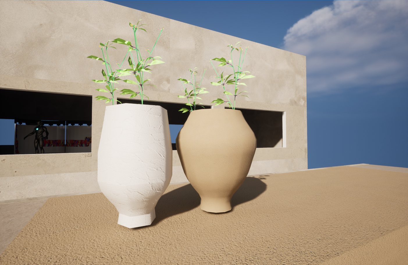
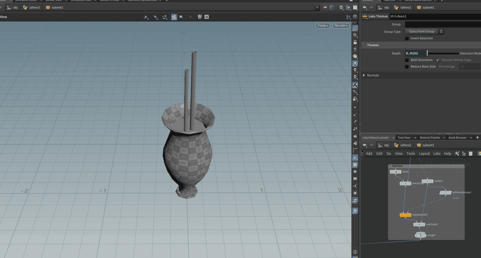
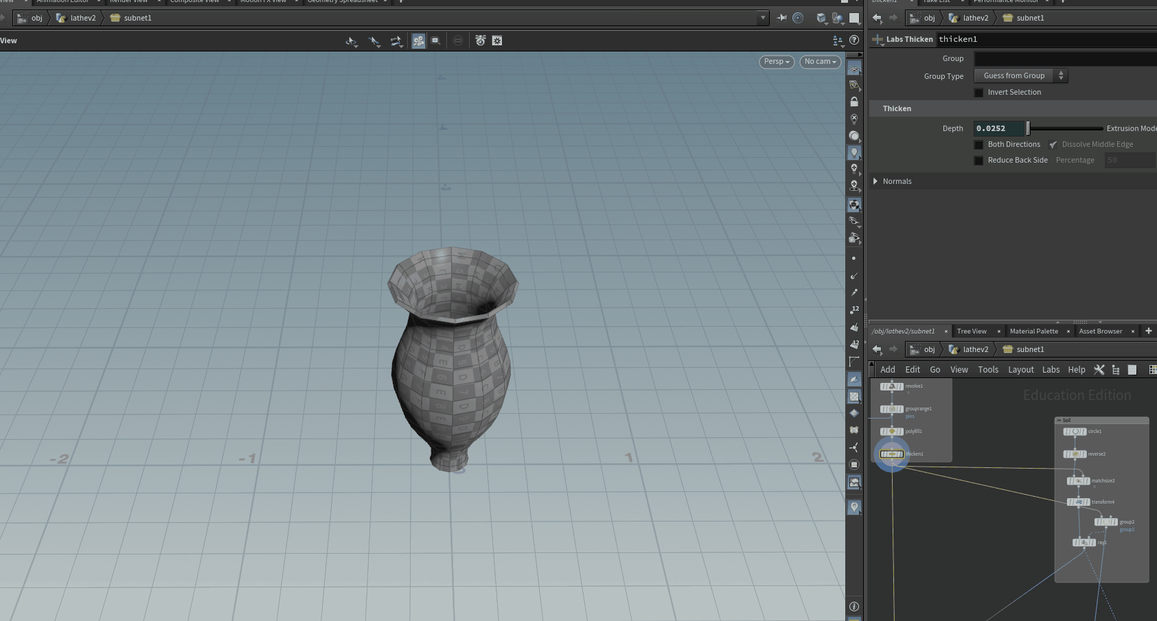
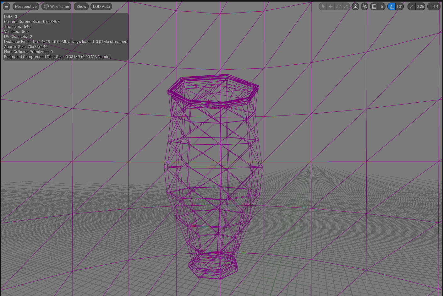
Procedural Flower Pot Modelling Tool v2 - Houdini + Unreal
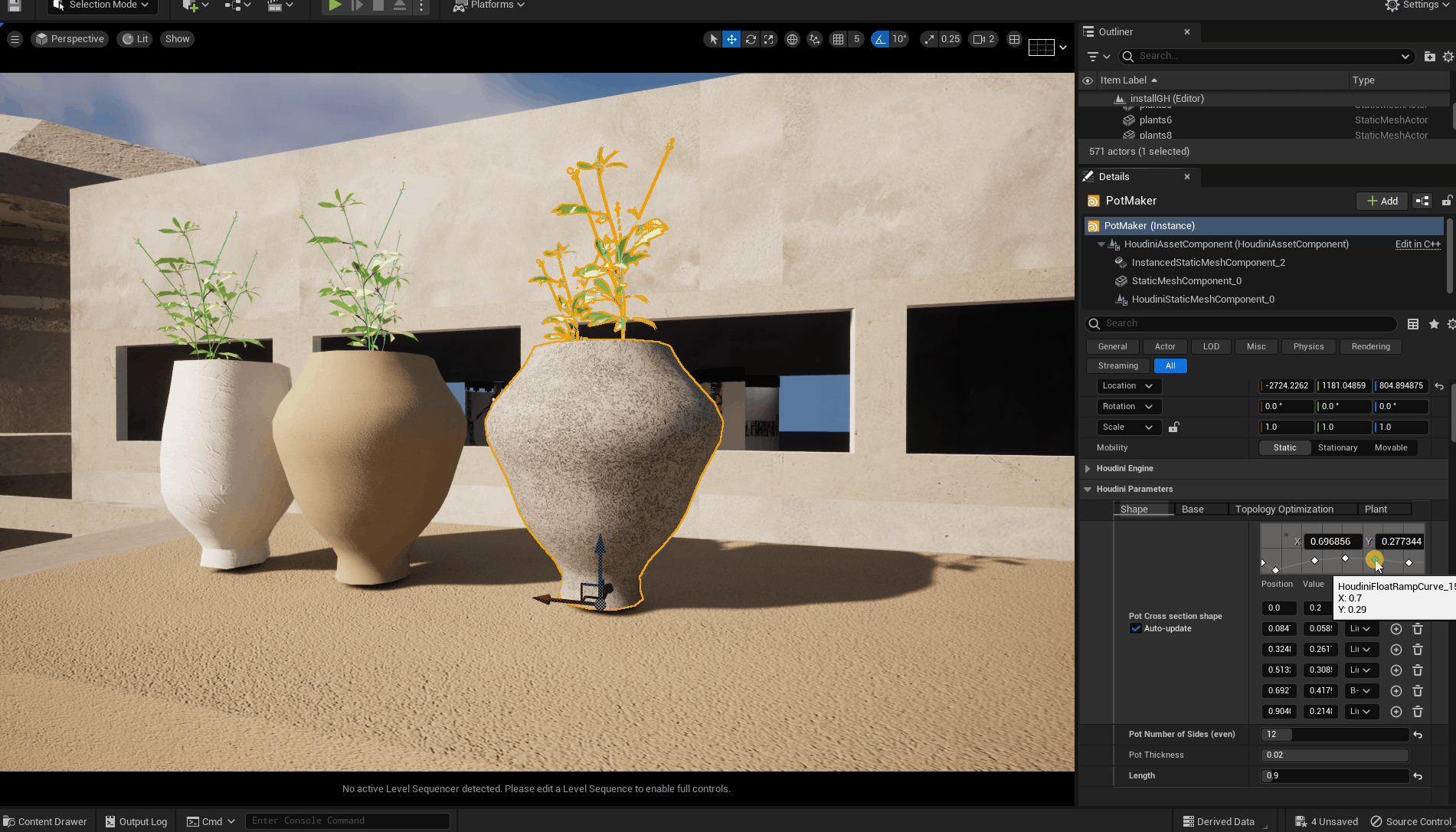
After sharing my last procedural modelling tool, a lot of the feedback I received pointed to checking out Houdini for Unreal Engine. Houdini’s entire suite of simulation and modelling tools and pipelines are available to artists working with Unreal Engine via the Houdini Engine Plugin. Over the past few weeks, I have been experimenting with making various Digital Assets in Houdini and I want to share one of the first complete tools I have made that builds upon my knowledge of Unreal’s Geometry Script Plugin.
The goal of the second version of this tool was to improve upon precision and control in the design of the flower pot as well as allowing for more precise topology optimization options in a non-destructive modelling pipeline that can stay or deviate from a specific art direction. The artist should be able to describe the cross-section of the pot as the basis of the object’s shape grammar or organising rules. It should also include an option to place plants in the pot, a feature that was computationally expensive in the previous iteration of the tool. Overall, the tool should allow the artist to iteratively design an asset library of different potted plants with a specific art direction.
The tool is made in Houdini and run in the Unreal Engine Editor as a Houdini Digital Assets. In the following paragraphs, I will describe the technical implementation of the tool through both software packages and my general insight into procedural modelling from the perspective of a media artist.
How It Works
The tool exposes a simple interface consisting of four tabs for modelling the pot through a few constrained parameters. The artist designs the shape of the pot by drawing a curve to represent the cross-section. They can optionally include a base for the pot, in the same silhouette. The artist can also procedurally place plants on the soil inside the pots, specifying the amount, scaling and placement variation inside the pot.
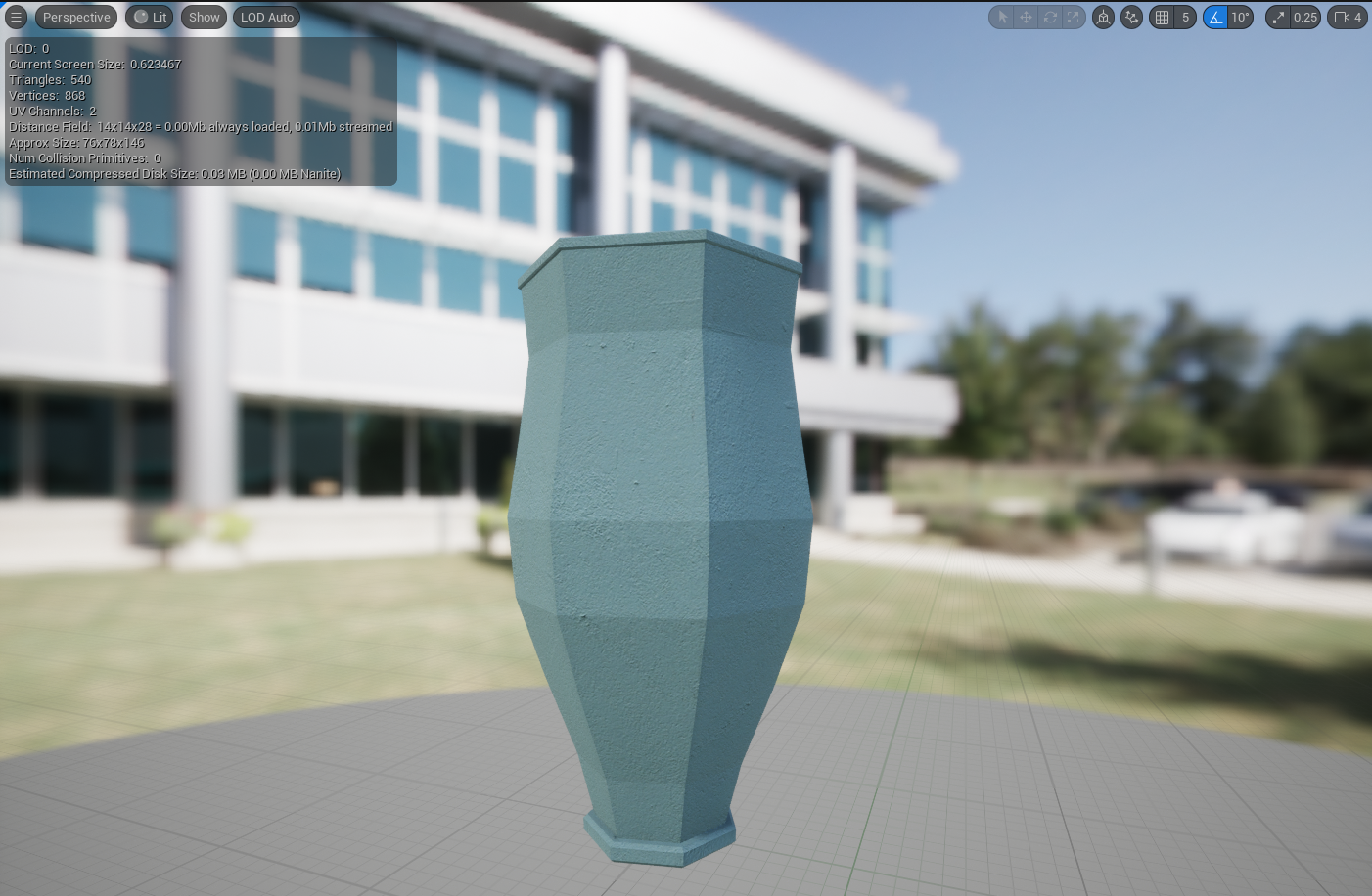
They can then bake out their static mesh, with a single material slot assigned and collision enabled. The final mesh produced for this demo has 256 triangles. It would be suitable for implementation in games with modern graphics hardware or upscaled for use as a prop in a cinematic render, as I will be doing.
Technical Overview
The process for making the tool in Houdini is theoretically similar to Unreal’s Geometry script with a few key differences.
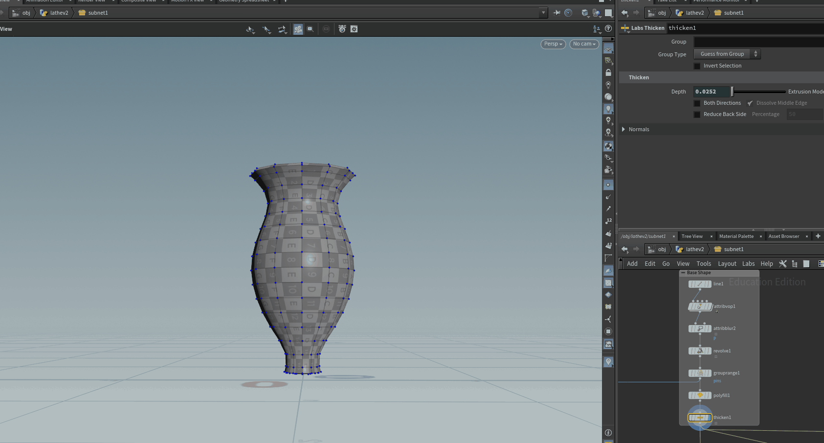
The base form is made by displacing a line along the vertical axis to produce the cross-section of the shape. This cross-section is then revolved and thickened to produce the pot. The only caveat here being the Polyfill Surface Operator in Houdini demands even numbered divisions to properly thicken the shape.
Things I learned
Although the resulting tool is functionally similar to the version I have already built using Unreal's Geometry Script, Houdini proceduralism driven by its core makes the process of implementing the tool a lot more intuitive and extendable. For example, it would be quite simple to introduce procedural fracturing or a rigid body simulation to crack the mesh as a visual effect.
Houdini is often described as being notoriously difficult to understand. However, I found that an understanding of the core principle of points and attributes as data in a processing pipeline you design is sufficient for an artist to exercise their creativity. It offers high-level convenience for example with the Revolve or Copy To Point Surface Operators as well as low-level bespoke design through VEX and Vops.
Combined with Unreal’s stellar real-time rendering and interaction mechanics via Blueprint, Houdini can greatly transform your scope. In the upcoming point, I will delve deeper into extending some of these concepts for world-building and experience design.
References:
https://www.sidefx.com/tutorials/
Procedural Fence Modelling | Houdini 19.5 | Houdini Zone |
Intro to Procedural Modelling in Houdini - Beginner Vase Generator

A Point Group is then created by isolating the bottom edge and used to extrude the base. An additional Point Group around the top edge is used as guide geometry to ray-cast a circle to form the soil layer. Points are then scattered onto this circle/soil layer as locations for the plants. These point groups and attributes ensure that regardless of the shape described, the placement of the soil and plants remains consistently proportional to where they would appear in real life.
The rest of the node graph merges the different geometry branches into switches, allowing the artist to specify if they want to include plants or the base per variation via a toggle switch.
The final layer of processing handles the assignment of a referenced material from the host Unreal Engine Project and topology optimization settings, allowing the user to reduce the polygon count by percentage before baking the output mesh.
In Unreal Engine, these options are available in the details panel of the Houdini Digital Asset.
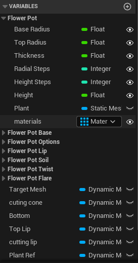
Procedural Flower Pot Modelling Tool
As part of my exploration of procedural modelling in Unreal Engine 5, I decided to design and build a tool to allow me to model flower pots of different forms for an upcoming cinematic garden scene. Using a procedural tool, rather than traditional polygonal modelling, would allow me to iterate quickly and generate an assets library with a lot of visual variety. My intentions were to make a tool flexible enough to result in visual variety quickly in a non-destructive workflow as well as heeding a specific art direction.
Over the past few weeks, I have been exploring Unreal Engine’s Geometry Script plugin, by building a few simple tools. As an artist slowly building up my technical skills in Unreal, proceduralism is especially attractive as it allows me to systematise creative processes. By thinking in terms of a pipeline to manipulate data to achieve specific artistic results, I am able to save a lot of time and also non-destructively deviate from the creative process resulting in serendipitous rewards.
However, thinking procedural is not always automatic and it often requires upfront planning to understand the shape grammar of the chosen object. A flower pot was a good choice with a fairly complex shape grammar, consisting usually of curved/revolved/flared forms, which can be translated into a series of steps and constraints. It would be a great way to test and improve my knowledge of Blueprints in Unreal.
My reference objects in the research stage were modern clay, concrete ceramic pots as well as traditional earthen pots from Ghana. I also wanted the resulting tool to be able to diverge from this art direction by exposing some of the more granular controls of the geometry.
The result tools start as a base conical form with a conditional bottom rim and lip that can be attached to the form. The user can particularise specific parts of the pot such as making the curve more concave or convex or reducing the sides to match the references. As seen from these five different pots, you can very quickly produce related or divergent forms by tweaking a few constrained dimensions.

Technical overview
The form is based on the append cone node with the critical dimension being the bottom and top radii, and the height. The thickness of the pot, the location of the rim and lip as well as the ground plane are then specified as ratios of the critical dimensions. This ensures that the base shape remains consistent.
The form is built in sequence making use of Compute Meshes which are then passed as Tool Meshes in boolean operations on the base Dynamic Mesh. This sequential process is great for debugging, allowing you to step through the design process. However, using Compute Meshes also reduces the CPU load.
The artist can also specific polygon count, assign materials to the pot and to the ground/soil, enable collision and then bake the dynamic mesh to a static mesh in the project’s content directory.
Another feature I was keen on adding was the option to place a plant mesh in the pot. To achieve this, the user can copy an existing static mesh and append it to the dynamic mesh they are modelling. The obvious drawback of this is that the copy operation tends to be computationally heavy, and breaks the responsiveness of the tool, hence I omitted it from the final version.

Conclusion
The key advantages of designing and making a tool like that are the insights into procedural modelling techniques as well as being able to produce variety quickly. The final mesh from the example has about 500 triangles and might be too heavy for traditional games but would work fine for my cinematic scene. The current setup could also be improved to make UV seaming and unwrapping a bit more consistent across all the forms; however, it works all right for solid colour materials, computed on the GPU in the pixel shader, reducing overall texture cost. However, modelling via this lack of extremely precise control over points/vertices is something the Geometry Script plugin could build upon in the future.
The target platform for the meshes is Windows /PC and not mobile or older generation consoles.
I am still digging deeper into Geometry Script but I am still very impressed by its flexibility, especially when working on a project alone. However, all the concepts can be refined and abstracted for other projects or users.
In a subsequent post, I will share the same tool made in Houdini as Digital Asset for Unreal. Houdini being purpose-built for proceduralism significantly reduces the complexity as well as extending the possible variations from the tool. The Houdini tool works by displacing and revolving a curve to produce the form.
Unreal Engine’s Geometry Script is far from being a replacement for Houdini however the overarching approach to procedural extend to both frameworks.
Procedural Signpost Tool
A quick demo of a procedural tool that allows artists to create Signposts in editor in Unreal Engine 5. The tool uses the Geometry Script Plugin, a collection of functions for procedural modelling through Blueprints in Unreal. The tool is made by joining dynamic meshes with constrained parameters together. This allows for a lot of variation and customization.
Further improvement can be built on top of this for different styles of street signs that are not rectangular or circular.
More Information on Geometry Script here
Procedural Bollards Tool
This tool allows you to make over five variations for bollards in editor in unreal. I demonstrate tweaking the various parameters exposed in the blueprint in order to make the bollards. The Dynamic Meshes are then converted to Static Meshes using modeling mode.
Bollards are used in cities to obstruct movements. By using a procedural modeling tool in engine, artists can quickly experiment with different kinds of bollards/assets in the context of their environment.
Geometry Script is an experimental plugin in Unreal Engine 5 that allows users to write scripts for procedural modeling.